Gears sections 9 - 12
Section 9: Worm meshEdit
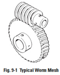
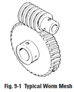
The worm mesh is another gear type used for connecting skew shafts, usually 90°. See Figure 9-1. Worm meshes are characterized by high velocity ratios. Also, they offer the advantage of higher load capacity associated with their line contact in contrast to the point contact of the crossed-helical mesh.
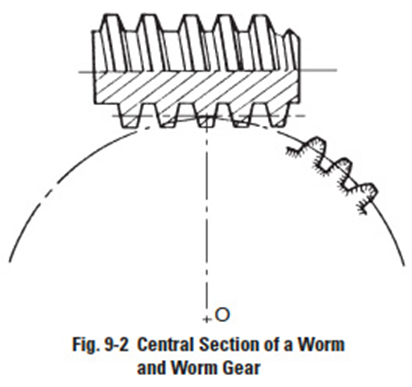
Figure 9-2
9.1 Worm Mesh GeometryEdit
Although the worm tooth form can be of a variety, the most popular is equivalent to a V-type screw thread, as in Figure 9-1. The mating worm gear teeth have a helical lead. (Note: The name "worm wheel" is often used interchangeably with "worm gear".) A central section of the mesh, taken through the worm's axis and perpendicular to the worm gear's axis, as shown in Figure 9-2, reveals a rack-type tooth of the worm, and a curved involute tooth form for the worm gear. However, the involute features are only true for the central section. Sections on either side of the worm axis reveal nonsymmetric and non-involute tooth profiles. Thus, a worm gear mesh is not a true involute mesh. Also, for conjugate action, the centre distance of the mesh must be an exact duplicate of that used in generating the worm gear.
To increase the length-of-action, the worm gear is made of a throated shape to wrap around the worm.
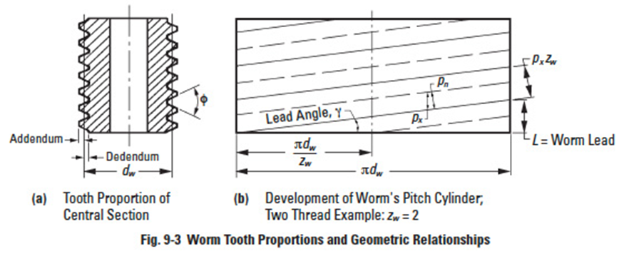
Figure 9-3
9.1.1 Worm Tooth ProportionsEdit
Worm tooth dimensions, such as addendum, dedendum, pressure angle, etc., follow the same standards as those for spur and helical gears. The standard values apply to the central section of the mesh. See Figure 9-3a. A high pressure angle is favoured and in some applications values as high as 25° and 30° are used.
9.1.2 Number Of ThreadsEdit
The worm can be considered resembling a helical gear with a high helix angle.
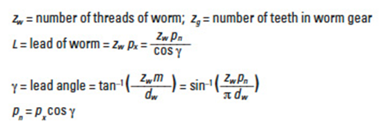
For extremely high helix angles, there is one continuous tooth or thread. For slightly smaller angles, there can be two, three or even more threads. Thus, a worm is characterized by the number of threads, zw.
9.1.3 Pitch Diameters, Lead and Lead AngleEdit
Referring to Figure 9-3:
where:
9.1.4 Centre DistanceEdit
9.2 Cylindrical Worm Gear CalculationsEdit
Cylindrical worms may be considered cylindrical type gears with screw threads. Generally, the mesh has a 90° shaft angle. The number of threads in the worm is equivalent to the number of teeth in a gear of a screw type gear mesh.
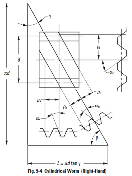
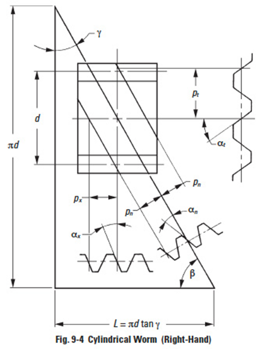
Figure 9-4
Thus, a one-thread worm is equivalent to a one-tooth gear; and two-threads equivalent to two-teeth, etc. Referring to Figure 9-4', for a lead angle ɣ, measured on the pitch cylinder, each rotation of the worm makes the thread advance one lead.
There are four worm tooth profiles in JIS B 1723, as defined below.
Type I Worm: This worm tooth profile is trapezoid in the radial or axial plane.
Type II Worm: This tooth profile is trapezoid viewed in the normal surface.
Type III Worm: This worm is formed by a cutter in which the tooth profile is trapezoid form viewed from the radial surface or axial plane set at the lead angle. Examples are milling and grinding profile cutters.
Type IV Worm: This tooth profile is involute as viewed from the radial surface or at the lead angle. It is an involute helicoid, and is known by that name.
Type III worm is the most popular. In this type, the normal pressure angle αn has the tendency to become smaller than that of the cutter, αc.
Per JIS, Type III worm uses a radial module mt and cutter pressure angle αc = 20° as the module and pressure angle. A special worm hob is required to cut a Type III worm gear. Standard values of radial module, mt, are presented in Table 9-1.
Table 9-1
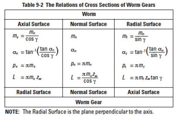
Table 9-2
Because the worm mesh couples nonparallel and nonintersecting axes, the radial surface of the worm, or radial cross section, is the same as the normal surface of the worm gear.
Similarly, the normal surface of the worm is the radial surface of the worm gear. The common surface of the worm and worm gear is the normal surface. Using the normal module, mn, is most popular. Then, an ordinary hob can be used to cut the worm gear.
Table 9-2' presents the relationships among worm and worm gear radial surfaces, normal surfaces, axial surfaces, module, pressure angle, pitch and lead.
Figure 9-4
Reference to Figure 9-4' can help the understanding of the relationships in Table 9-2. They are similar to the relations in Formulas (6-11) and (6-12) that the helix angle β be substituted by (90° – ɣ). We can consider that a worm with lead angle ɣ is almost the same as a screw gear with helix angle (90° – ɣ).
Table 9-3
Figure 9-5
9.2.1 Axial Module Worm GearsEdit
Table 9-3' presents the equations, for dimensions shown in Figure 9-5, for worm gears with axial module, mx, and normal pressure angle αn = 20°.
Table 9-4
9.2.2 Normal Module System Worm GearsEdit
The equations for normal module system worm gears are based on a normal module, mn, and normal pressure angle, αn = 20°. See Table 9-4.
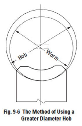
Figure 9-6
9.3 Crowning Of The Worm Gear ToothEdit
Crowning is critically important to worm gears (worm wheels). Not only can it eliminate abnormal tooth contact due to incorrect assembly, but it also provides for the forming of an oil film, which enhances the lubrication effect of the mesh. This can favourably impact endurance and transmission efficiency of the worm mesh. There are four methods of crowning worm gears:
- Cut Worm Gear With A Hob Cutter Of Greater Pitch Diameter Than The Worm.
A crownless worm gear results when it is made by using a hob that has an identical pitch diameter as that of the worm. This crownless worm gear is very difficult to assemble correctly. Proper tooth contact and a complete oil film are usually not possible.
However, it is relatively easy to obtain a crowned worm gear by cutting it with a hob whose pitch diameter is slightly larger than that of the worm. This is shown in Figure 9-6. This creates teeth contact in the centre region with space for oil film formation.
- Recut With Hob Centre Distance Adjustment.
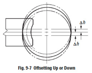
The first step is to cut the worm gear at standard centre distance. This results in no crowning. Then the worm gear is finished with the same hob by recutting with the hob axis shifted parallel to the worm gear axis by ±Δh. This results in a crowning effect, shown in Figure 9-7.
Figure 9-7
- Hob Axis Inclining Δθ From Standard Position.
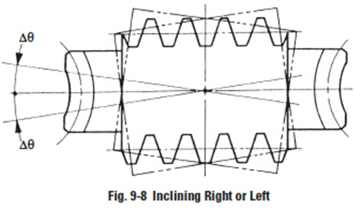
Figure 9-8
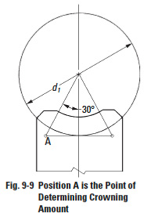
Figure 9-9
In standard cutting, the hob axis is oriented at the proper angle to the worm gear axis. After that, the hob axis is shifted slightly left and then right, Δθ, in a plane parallel to the worm gear axis, to cut a crown effect on the worm gear tooth. This is shown in Figure 9-8. Only method 1 is popular. Methods 2 and 3 are seldom used.
- Use A Worm With A Larger Pressure Angle Than The Worm Gear.
This is a very complex method, both theoretically and practically. Usually, the crowning is done to the worm gear, but in this method the modification is on the worm. That is, to change the pressure angle and pitch of the worm without changing the pitch line parallel to the axis, in accordance with the relationships shown in Equations 9-4:
In order to raise the pressure angle from before change, αx', to after change, αx, it is necessary to increase the axial pitch, px', to a new value, px, per Equation (9-4). The amount of crowning is represented as the space between the worm and worm gear at the meshing point A in Figure 9-9.
This amount may be approximated by the following equation:
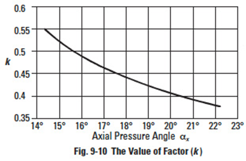
Figure 9-10
where:
d1= Pitch diameter of worm
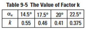
k= Factor from Table 9-5 and Figure 9-10'''
px= Axial pitch after change
px' = Axial pitch before change
Table 9-6
An example of calculating worm crowning is shown in Table 9-6.
Because the theory and equations of these methods are so complicated, they are beyond the scope of this treatment. Usually, all stock worm gears are produced with crowning.
9.4 Self-Locking Of Worm Mesh'Edit
Self-locking is a unique characteristic of worm meshes that can be put to advantage. It is the feature that a worm cannot be driven by the worm gear. It is very useful in the design of some equipment, such as lifting, in that the drive can stop at any position without concern that it can slip in reverse. However, in some situations it can be detrimental if the system requires reverse sensitivity, such as a servomechanism.
Self-locking does not occur in all worm meshes, since it requires special conditions as outlined here. In this analysis, only the driving force acting upon the tooth surfaces is considered without any regard to losses due to bearing friction, lubricant agitation, etc. The governing conditions are as follows:
Let Fu1 = tangential driving force of worm
where:
αn = normal pressure angle
ɣ = lead angle of worm
µ = coefficient of friction
Fn = normal driving force of worm
If Fu1 > 0 then there is no self-locking effect at all. Therefore, Fu1 ≤ 0 is the critical limit of self-locking.
Let αn in Equation (9-6) be 20°, then the condition:
Fu1 ≤ 0 will become:
(cos 20° sin ɣ – µ cos ɣ) ≤ 0
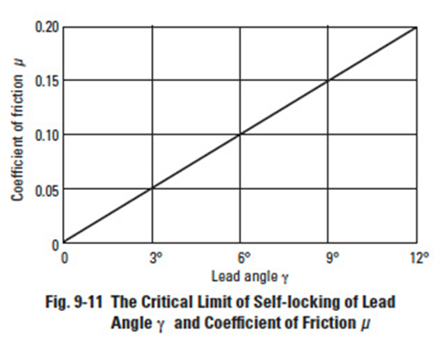
Figure 9-11
Figure 9-11' shows the critical limit of self-locking for lead angle ɣ and coefficient of friction µ. Practically, it is very hard to assess the exact value of coefficient of friction µ. Further, the bearing loss, lubricant agitation loss, etc. can add many side effects. Therefore, it is not easy to establish precise self-locking conditions. However, it is true that the smaller the lead angle ɣ, the more likely the self-locking condition will occur.
Section 10: Tooth ThicknessEdit
There are direct and indirect methods for measuring tooth thickness. In general, there are three methods:
- Chordal Thickness Measurement
- Span Measurement
- Over Pin or Ball Measurement
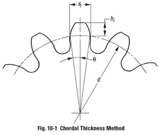
Figure 10-1
10.1 Chordal Thickness MeasurementEdit
This method employs a tooth caliper that is referenced from the gear's outside diameter. Thickness is measured at the pitch circle. See Figure 10-1.
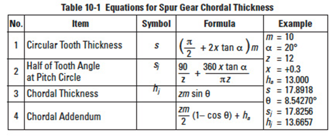
Table 10-1
10.1.1 Spur GearsEdit
Table 10-1 presents equations for each chordal thickness measurement.
Table 10-2
10.1.2 Spur Racks And Helical RacksEdit
The governing equations become simple since the rack tooth profile is trapezoid, as shown in
Table 10-2.
Table 10-3
Table 10-4
Table 10-5
Figure 10-2
10.1.3 Helical GearsEdit
The chordal thickness of helical gears should be measured on the normal surface basis as shown in Table 10-3. Table 10-4 presents the equations for chordal thickness of helical gears in the radial system. See Figure 10-2 and Table 10-5 for Gleason straight bevel gears.
Table 10-6
Table 10-6 presents equations for chordal thickness of a standard straight bevel gear.
If a standard straight bevel gear is cut by a Gleason straight bevel cutter, the tooth angle should be adjusted according to:
Table 10-7
This angle is used as a reference in determining the circular tooth thickness, s, in setting up the gear cutting machine.
Table 10-7 presents equations for chordal thickness of a Gleason spiral bevel gear.
Figure 10-3
Figure 10-3 shows how to determine the circular tooth thickness factor K for Gleason spiral bevel gears.
The calculations of circular thickness of a Gleason spiral bevel gear are so complicated that we do not intend to go further in this presentation.
Table 10-8
10.1.5 Worms And Worm GearsEdit
Table 10-8 presents equations for chordal thickness of axial module worms and worm gears.
Table 10-9
Table 10-9 contains the equations for chordal thickness of normal module worms and worm gears.
10.2 Span Measurement Of TeethEdit
Span measurement of teeth, sm, is a measure over a number of teeth, zm, made by means of a special tooth thickness micrometer. The value measured is the sum of normal circular tooth thickness on the base circle, sbn, and normal pitch, pen (zm – 1).
10.2.1 Spur And Internal GearsEdit
Table 10-10
The applicable equations are presented in Table 10-10.
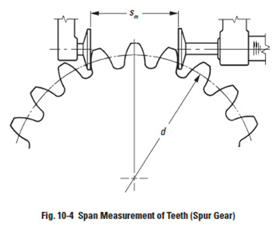
Figure 10-4
Figure 10-4 shows the span measurement of a spur gear. This measurement is on the outside of the teeth. For internal gears the tooth profile is opposite to that of the external spur gear. Therefore, the measurement is between the inside of the tooth profiles.
Table 10-11
Table 10-12
10.2.2 Helical GearsEdit
Tables 10-11 and 10-12 present equations for span measurement of the normal and the radial systems, respectively, of helical gears.
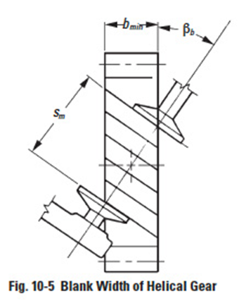
There is a requirement of a minimum blank width to make a helical gear span measurement. Let bmin be the minimum value for blank width. Then
where βb is the helix angle at the base cylinder,
From the above, we can determine that at least 3mm of Δb is required to make a stable measurement of sm.
Figure 10-6
Figure 10-7
10.3 Over Pin (Ball) MeasurementEdit
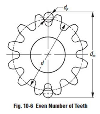
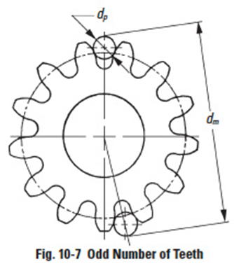
As shown in Figures 10-6 and 10-7, measurement is made over the outside of two pins that are inserted in diametrically opposite tooth spaces, for even tooth number gears; and as close as possible for odd tooth number gears.
Figure 10-8
Figure 10-9
Figure 10-10
Figure 10-11
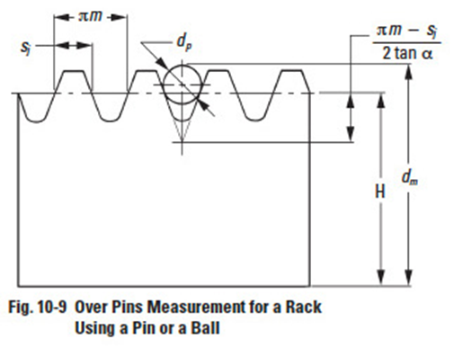
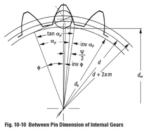
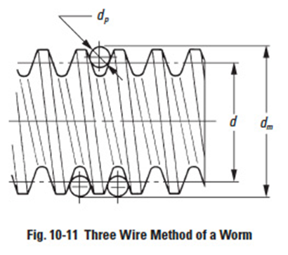
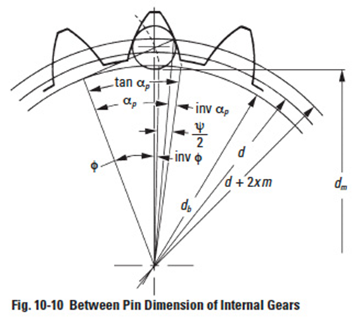
The procedure for measuring a rack with a pin or a ball is as shown in Figure 10-9 by putting pin or ball in the tooth space and using a micrometer between it and a reference surface. Internal gears are similarly measured, except that the measurement is between the pins. See Figure 10-10. Helical gears can only be measured with balls. In the case of a worm, three pins are used, as shown in Figure 10-11. This is similar to the procedure of measuring a screw thread. All these cases are discussed in detail in the following sections.
Note that gear literature uses "over pins" and "over wires" terminology interchangeably. The "over wires" term is often associated with very fine pitch gears because the diameters are accordingly small.
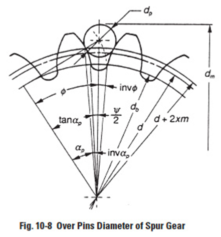
10.3.1 Spur Gears In measuring a gear, the size of the pin must be such that the over pins measurement is larger than the gear's outside diameter. An ideal value is one that would place the point of contact (tangent point) of pin and tooth profile at the pitch radius. However, this is not a necessary requirement. Referring to Figure 10-8, following are the equations for calculating the over pins measurement for a specific tooth thickness, s, regardless of where the pin contacts the tooth profile:Edit
For even number of teeth:
For odd number of teeth:
where the value of φ1 is obtained from:
When tooth thickness, s, is to be calculated from a known over pins measurement, dm, the above equations can be manipulated to yield:
Where
In measuring a standard gear, the size of the pin must meet the condition that its surface should have the tangent point at the standard pitch circle. While, in measuring a shifted gear, the surface of the pin should have the tangent point at the d + 2xm circle.
Table 10-13
Table 10-14
Table 10-15
The ideal diameters of pins when calculated from the equations of Table 10-13 may not be practical. So, in practice, we select a standard pin diameter close to the ideal value. After the actual diameter of pin dp is determined, the over pin measurement dm can be calculated from Table 10-14.
Table 10-15 is a dimensional table under the condition of module m = 1 and pressure angle α = 20° with which the pin has the tangent point at d + 2xm circle.
Table 10-16
Table 10-16A
10.3.2 Spur Racks And Helical RacksEdit
In measuring a rack, the pin is ideally tangent with the tooth flank at the pitch line. The equations in Table 10-16 can, thus, be derived. In the case of a helical rack, module m, and pressure angle α, in Table 10-16, can be substituted by normal module, mn, and normal pressure angle, αn, resulting in Table 10-16A.
Table 10-17
Table 10-18
Table 10-19
10.3.3 Internal GearsEdit
As shown in Figure 10-10, measuring an internal gear needs a proper pin which has its tangent point at d + 2xm circle. The equations are in Table 10-17 for obtaining the ideal pin diameter. The equations for calculating the between pin measurement, dm, are given in Table 10-18.
Table 10-19, lists ideal pin diameters for standard and profile shifted gears under the condition of module m = 1 and pressure angle α = 20°, which makes the pin tangent to the pitch circle d + 2xm.
Table 10-20
10.3.4 Helical GearsEdit
The ideal pin that makes contact at the d + 2xm mn pitch circle of a helical gear can be obtained from the same above equations, but with the teeth number z substituted by the equivalent (virtual) teeth number zv. Table 10-20 presents equations for deriving over pin diameters.
Table 10-21
Table 10-22
Table 10-21 presents equations for calculating over pin measurements for helical gears in the normal system.
Table 10-22 and Table 10-23 present equations for calculating pin measurements for helical gears in the radial (perpendicular to axis) system.
Table 10-23
10.3.5 Three Wire Method Of Worm MeasurementEdit
The teeth profile of Type III worms which are most popular are cut by standard cutters with a pressure angle αc = 20°. This results in the normal pressure angle of the worm being a bit smaller than 20°. The equation below shows how to calculate a Type III worm in an AGMA system.
Table 10-24
Table 10-25
where:
r = Worm Pitch Radius
rc = Cutter Radius
zw = Number of Threads
ɣ = Lead Angle of Worm
The exact equation for a three wire method of Type III worm is not only difficult to comprehend, but also hard to calculate precisely. We will introduce two approximate calculation methods here:
(a) Regard the tooth profile of the worm as a linear tooth profile of a rack and apply its equations. Using this system, the three wire method of a worm can be calculated by Table 10-24.
These equations presume the worm lead angle to be very small and can be neglected. Of course, as the lead angle gets larger, the equations' error gets correspondingly larger. If the lead angle is considered as a factor, the equations are as in Table 10-25.
Table 10-26
Table 10-27
Table 10-28
Table 10-29
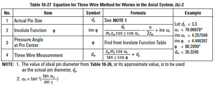
(b) Consider a worm to be a helical gear. This means applying the equations for calculating over pins measurement of helical gears to the case of three wire method of a worm. Because the tooth profile of Type III worm is not an involute curve, the method yields an approximation. However, the accuracy is adequate in practice.
Tables 10-26' and 10-27 contain equations based on the axial system. Tables 10-28 and 10-29 are based on the normal system.
Table 10-28 shows the calculation of a worm in the normal module system. Basically, the normal module system and the axial module system have the same form of equations. Only the notations of module make them different.
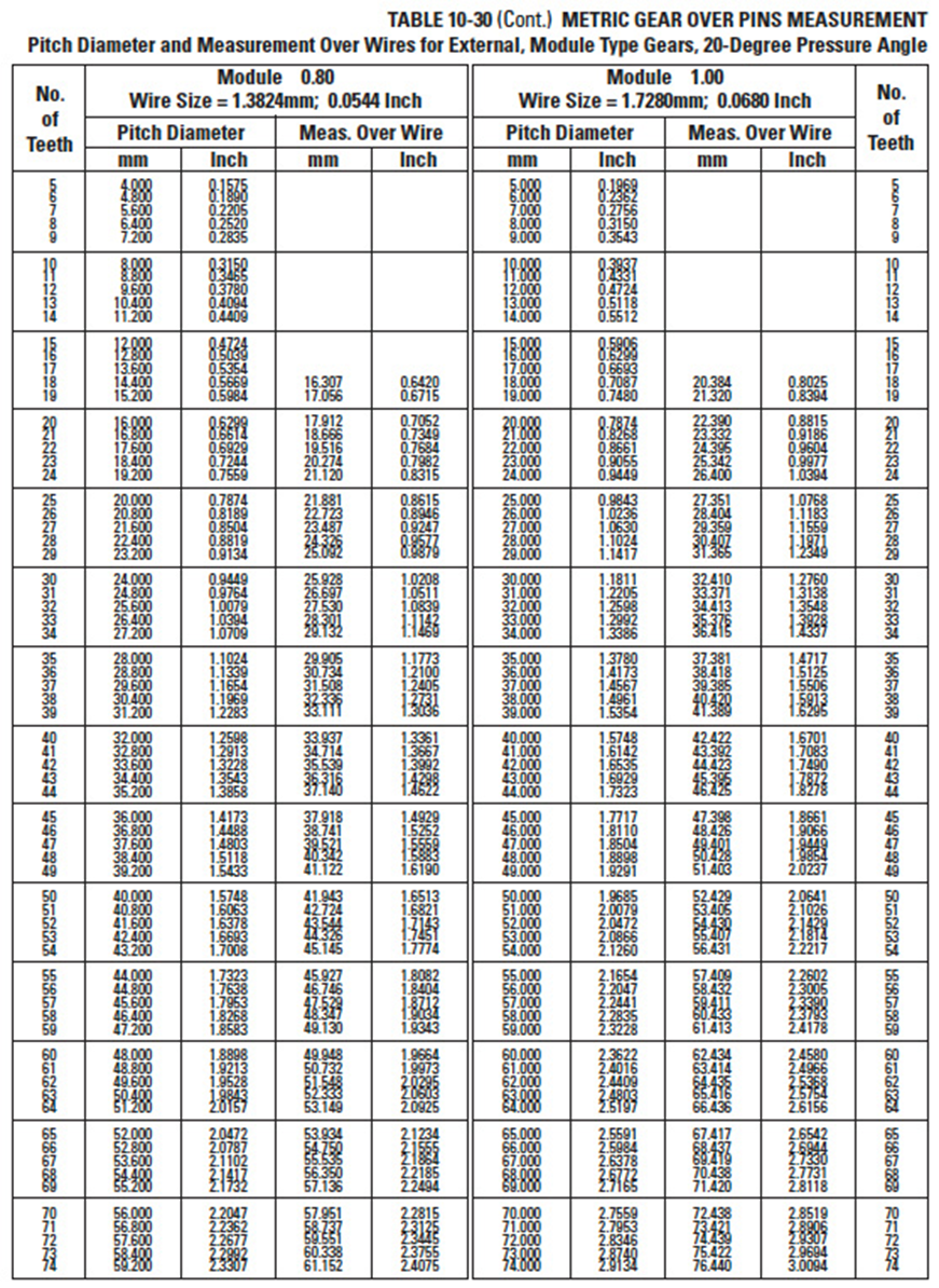
Table 10-30
Table 10-30 cont.
Table 10-30 cont.
Table 10-30 cont.
Table 10-30 cont.
Table 10-30 cont.
Table 10-30 cont.
Table 10-30 cont.
Table 10-30 cont.
10.4 Over Pins Measurements For Fine Pitch Gears With Specific Numbers Of TeethEdit
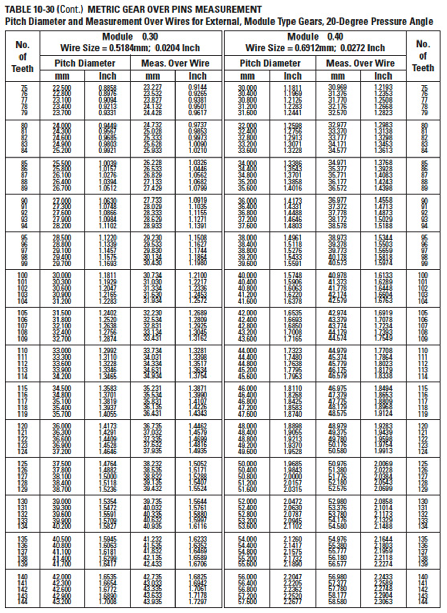
Table 10-30, Table-30 part 2, Table-30 part 3, Table-30 part 4, Table-30 part 5, Table-30 part 6, Table-30 part 7, Table-30 part 8 and Table-30 part 9 presents measurements for metric gears. These are for standard ideal tooth thicknesses. Measurements can be adjusted accordingly to backlash allowance and tolerance; i.e., tooth thinning.
Section 11: Contact ratioEdit
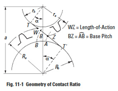
To assure continuous smooth tooth action, as one pair of teeth ceases action a succeeding pair of teeth must already have come into engagement. It is desirable to have as much overlap as is possible. A measure of this overlap action is the contact ratio. This is a ratio of the length of the line-of-action to the base pitch. Figure 11-1 shows the geometry for a spur gear pair, which is the simplest case, and is representative of the concept for all gear types. The length-of-action is determined from the intersection of the line-of-action and the outside radii. The ratio of the length-of-action to the base pitch is determined from:
It is good practice to maintain a contact ratio of 1.2 or greater. Under no circumstances should the ratio drop below 1.1, calculated for all tolerances at their worst case values.
A contact ratio between 1 and 2 means that part of the time two pairs of teeth are in contact and during the remaining time one pair is in contact. A ratio between 2 and 3 means 2 or 3 pairs of teeth are always in contact. Such a high ratio is generally not obtained with external spur gears, but can be developed in the meshing of internal gears, helical gears, or specially designed nonstandard external spur gears.
When considering all types of gears, contact ratio is composed of two components:
- Radial contact ratio (plane of rotation perpendicular to axes), εα
- Overlap contact ratio (axial), εβ
The sum is the total contact ratio, εɣ.
The overlap contact ratio component exists only in gear pairs that have helical or spiral tooth forms.
11.1 Radial Contact Ratio Of Spur And Helical Gears, εαEdit
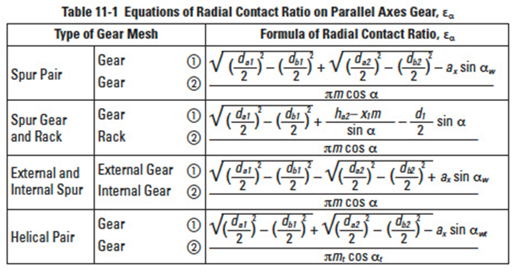
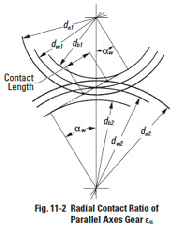
The equations for radial (or plane of rotation) contact ratio for spur and helical gears are given in Table 11-1, with reference to Figure 11-2.
When the contact ratio is inadequate, there are three means to increase it. These are somewhat obvious from examination of Equation (11-1).
Table 11-1
Decrease the pressure angle. This makes a longer line-of-action as it extends through the region between the two outside radii.
- Increase the number of teeth. As the number of teeth increases and the pitch diameter grows, again there is a longer line-of-action in the region between the outside radii.
- Increase working tooth depth. This can be done by adding addendum to the tooth and thus increase the outside radius. However, this requires a larger dedendum, and requires a special tooth design.
An example of helical gear:
Note that in Table 11-1 only the radial or circular (plane of rotation) contact ratio is considered. This is true of both the spur and helical gear equations. However, for helical gears this is only one component of two. For the helical gear's total contact ratio, εɣ, the overlap (axial) contact ratio, εβ, must be added. See Paragraph 11.4.
11.2 Contact Ratio Of Bevel Gears, εαEdit
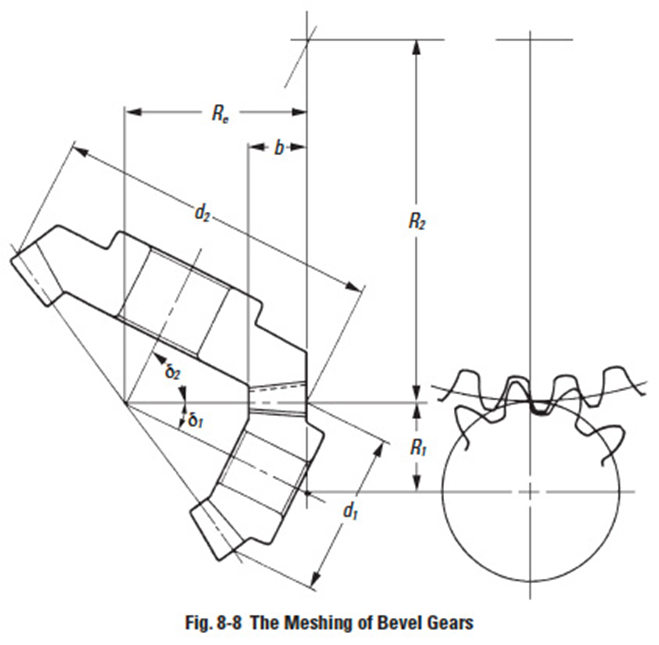
The contact ratio of a bevel gear pair can be derived from consideration of the equivalent spur gears, when viewed from the back cone. See Figure 8-8.
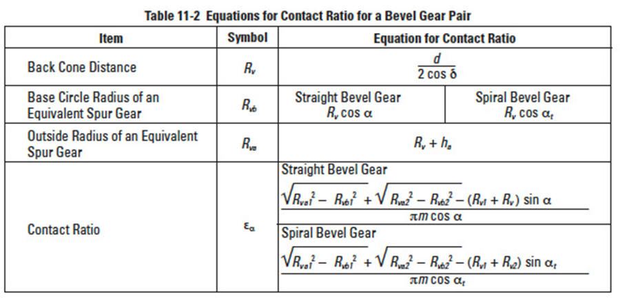
With this approach, the mesh can be treated as spur gears. Table 11-2 presents equations calculating the contact ratio.
Figure 8-8
Table 11-2
An example of spiral bevel gear (see Table 11-2):
11.3 Contact Ratio For Nonparallel And Nonintersecting Axes Pairs, εEdit
This group pertains to screw gearing and worm gearing. The equations are approximations by considering the worm and worm gear mesh in the plane perpendicular to worm gear axis and likening it to spur gear and rack mesh. Table 11-3 presents these equations.
Example of worm mesh:
11.4 Axial (Overlap) Contact Ratio, εβEdit
Helical gears and spiral bevel gears have an overlap of tooth action in the axial direction. This overlap adds to the contact ratio. This is in contrast to spur gears which have no tooth action in the axial direction.
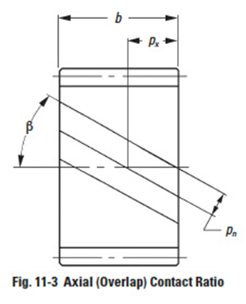
Figure 11-3
Table 11-3
Table 11-4
Thus, for the same tooth proportions in the plane of rotation, helical and spiral bevel gears offer a significant increase in contact ratio. The magnitude of axial contact ratio is a direct function of the gear width, as illustrated in Figure 11-3. Equations for calculating axial contact ratio are presented in Table 11-4.
It is obvious that contact ratio can be increased by either increasing the gear width or increasing the helix angle.
Section 12: Gear tooth modificationsEdit
Intentional deviations from the involute tooth profile are used to avoid excessive tooth load deflection interference and thereby enhances load capacity. Also, the elimination of tip interference reduces meshing noise. Other modifications can accommodate assembly misalignment and thus preserve load capacity.
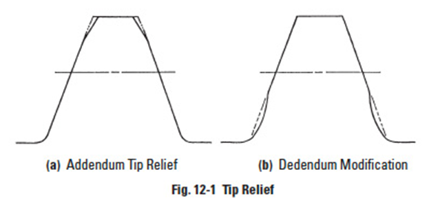
Figure 12-1
12.1 Tooth Tip ReliefEdit
There are two types of tooth tip relief. One modifies the addendum, and the other the dedendum. See Figure 12-1. Addendum relief is much more popular than dedendum modification.
12.2 Crowning And Side RelievingEdit
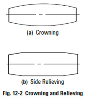
Crowning and side relieving are tooth surface modifications in the axial direction. See Figure 12-2.
Crowning is the removal of a slight amount of tooth from the centre on out to reach edge, making the tooth surface slightly convex. This method allows the gear to maintain contact in the central region of the tooth and permits avoidance of edge contact with consequent lower load capacity. Crowning also allows a greater tolerance in the misalignment of gears in their assembly, maintaining central contact.
Relieving is a chamfering of the tooth surface. It is similar to crowning except that it is a simpler process and only an approximation to crowning. It is not as effective as crowning.
12.3 Topping And SemitoppingEdit
In topping, often referred to as top hobbing, the top or outside diameter of the gear is cut simultaneously with the generation of the teeth. An advantage is that there will be no burrs on the tooth top. Also, the outside diameter is highly concentric with the pitch circle. This permits secondary machining operations using this diameter for nesting.
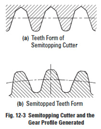
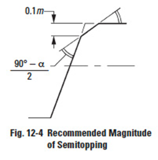
Semitopping is the chamfering of the tooth's top corner, which is accomplished simultaneously with tooth generation. Figure 12-3 shows a semitopping cutter and the resultant generated semitopped gear. Such a tooth tends to prevent corner damage. Also, it has no burr. The magnitude of semitopping should not go beyond a proper limit as otherwise it would significantly shorten the addendum and contact ratio. Figure 12-4 specifies a recommended magnitude of semitopping.
Both modifications require special generating tools. They are independent modifications but, if desired, can be applied simultaneously.
