Gears sections 5 - 8
Section 5: internal gearsEdit
5.1 Internal Gear CalculationsEdit
Calculation of a Profile Shifted Internal Gear
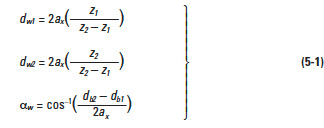
Figure 5-1 presents the mesh of an internal gear and external gear. Of vital importance is the operating (working) pitch diameters, dw, and operating (working) pressure angle, αw. They can be derived from center distance,ax, and Equations (5-1).
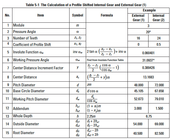
Table 5-1 shows the calculation steps.
It will become a standard gear calculation if x1 = x2= 0.
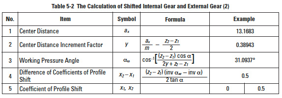
If the center distance, ax, is given, x1 and x2 would be obtained from the inverse calculation from item 4 to item 8 of Table 5-1. These inverse formulas are in Table 5-2.
Pinion cutters are often used in cutting internal gears and external gears. The actual value of tooth depth and root diameter, after cutting, will be slightly different from the calculation. That is because the cutter has a coefficient of shifted profile. In order to get a correct tooth profile, the coefficient of cutter should be taken into consideration.
5.2 Interference In Internal GearsEdit
Three different types of interference can occur with internal gears:
(a) Involute Interference
(b) Trochoid Interference
(c) Trimming Interference
(a) Involute Interference
This occurs between the dedendum of the external gear and the addendum of the internal gear. It is prevalent when the number of teeth of the external gear is small. Involute interference can be avoided by the conditions cited below:
where αa2 is the pressure angle seen at a tip of the internal gear tooth.
and αw is working pressure angle:
Equation (5-3) is true only if the outside diameter of the internal gear is bigger than the base circle:
For a standard internal gear, where α = 20°, Equation (5-5) is valid only if the number of teeth is z'2 > 34.
(b) Trochoid Interference
This refers to an interference occurring at the addendum of the external gear and the dedendum of the internal gear during recess tooth action. It tends to happen when the difference between the numbers of teeth of the two gears is small. Equation (5-6) presents the condition for avoiding trochoidal interference.
Here
where αa1 is the pressure angle of the spur gear tooth tip:
In the meshing of an external gear and a standard internal gear α = 20°, trochoid interference is avoided if the difference of the number of teeth, z'1 – z'2, is larger than 9.
(c) Trimming Interference
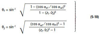
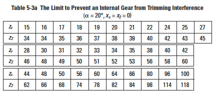
This occurs in the radial direction in that it prevents pulling the gears apart. Thus, the mesh must be assembled by sliding the gears together with an axial motion. It tends to happen when the numbers of teeth of the two gears are very close. Equation (5-9) indicates how to prevent this type of interference.
Here
This type of
interference can occur in the process of cutting an internal gear with a pinion cutter. Should that happen, there is danger of breaking the tooling. Table 5-3a shows the limit for the pinion cutter to prevent trimming interference when cutting a standard internal gear, with pressure angle 20°, and no profile shift, i.e., x'c = 0.
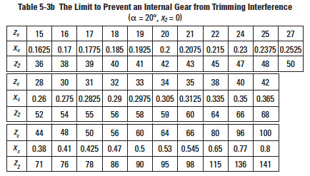
There will be an involute interference between the internal gear and the pinion cutter if the number of teeth of the pinion cutter ranges from 15 to 22 (z'c = 15 to 22). Table 5-3b shows the limit for a profile shifted pinion cutter to prevent trimming interference while cutting a standard internal gear. The correction, x'c, is the magnitude of shift which was assumed to be: x'c = 0.0075 z'c + 0.05.
There will be an involute interference between the internal gear and the pinion cutter if the number of teeth of the pinion cutter ranges from 15 to 19 (z'c = 15 to 19).
5.3 Internal Gear With Small Differences In Numbers Of TeethEdit
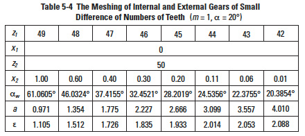
In the meshing of an internal gear and an external gear, if the difference in numbers of teeth of two gears is quite small, a profile shifted gear could prevent the interference. Table 5-4 is an example of how to prevent interference under the conditions of z'2 = 50 and the difference of numbers of teeth of two gears ranges from 1 to 8.
All combinations above will not cause involute interference or trochoid interference, but trimming interference is still there. In order to assemble successfully, the external gear should be assembled by inserting in the axial direction.
A profile shifted internal gear and external gear, in which the difference of numbers of teeth is small, belong to the field of hypocyclic mechanism, which can produce a large reduction ratio in one step, such as 1/100.
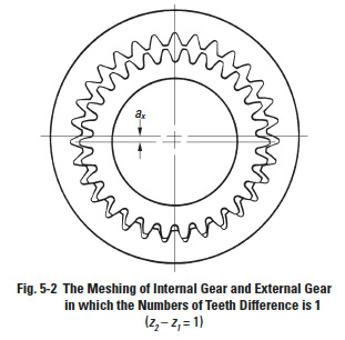
In Figure 5-2 the gear train has a difference of numbers of teeth of only 1; z'1 = 30 and z'2 = 31. This results in a reduction ratio of 1/30.
Section 6: helical gearsEdit
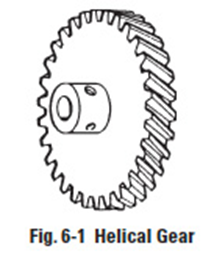
The helical gear differs from the spur gear in that its teeth are twisted along a helical path in the axial direction. It resembles the spur gear in the plane of rotation, but in the axial direction it is as if there were a series of staggered spur gears. See Figure 6-1. This design brings forth a number of different features relative to the spur gear, two of the most important being as follows:
- Tooth strength is improved because of the elongated helical wraparound tooth base support
- Contact ratio is increased due to the axial tooth overlap. Helical gears thus tend to have greater load carrying capacity than spur gears of the same size. Spur gears, on the other hand, have a somewhat higher efficiency.
Helical gears are used in two forms:
- Parallel shaft applications, which is the largest usage.
- Crossed-helicals (also called spiral or screw gears) for connecting skew shafts, usually at right angles.
6.1 Generation Of The Helical ToothEdit
The helical tooth form is involute in the plane of rotation and can be developed in a manner similar to that of the spur gear. However, unlike the spur gear which can be viewed essentially as two dimensional, the helical gear must be portrayed in three dimensions to show changing axial features.
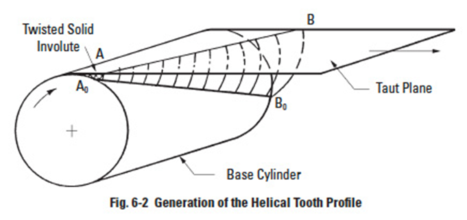
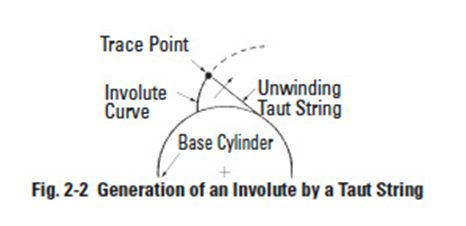
Referring to Figure 6-2, there is a base cylinder from which a taut plane is unwrapped, analogous to the unwinding taut string of the spur gear in Figure 2-2. On the plane there is a straight line AB, which when wrapped on the base cylinder has a helical trace AoBo. As the taut plane is unwrapped, any point on the line AB can be visualized as tracing an involute from the base cylinder. Thus, there is an infinite series of involutes generated by AB, all alike, but displaced in phase along a helix on the base cylinder.
Again, a concept analogous to the spur gear tooth development is to imagine the taut plane being wound from one base cylinder on to another as the base cylinders rotate in opposite directions. The result is the generation of a pair of conjugate helical involutes. If a reverse direction of rotation is assumed and a second tangent plane is arranged so that it crosses the first, a complete involute helicoid tooth is formed.
6.2 Fundamentals Of Helical TeethEdit
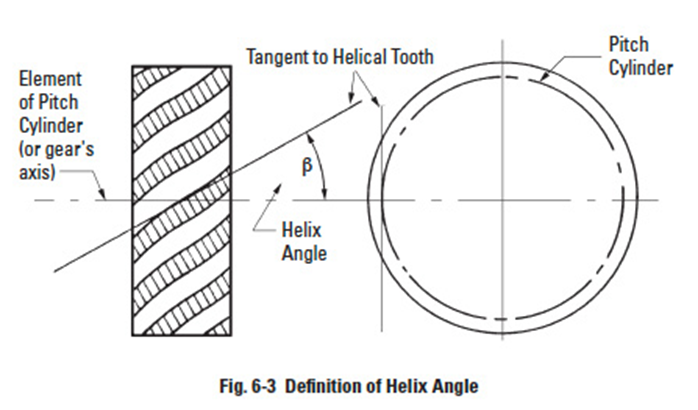
In the plane of rotation, the helical gear tooth is involute and all of the relationships governing spur gears apply to the helical. However, the axial twist of the teeth introduces a helix angle. Since the helix angle varies from the base of the tooth to the outside radius, the helix angle β is defined as the angle between the tangent to the helicoidal tooth at the intersection of the pitch cylinder and the tooth profile, and an element of the pitch cylinder. See Figure 6-3.
The direction of the helical twist is designated as either left or right. The direction is defined by the right-hand rule.
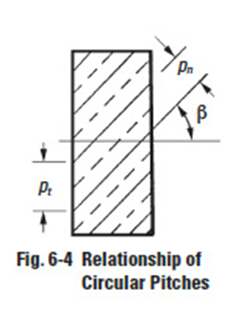
For helical gears, there are two related pitches – one in the plane of rotation and the other in a plane normal to the tooth. In addition, there is an axial pitch. Referring to Figure 6-4, the two circular pitches are defined and related as follows:
The normal circular pitch is less than the transverse radial pitch, pt, in the plane of rotation; the ratio between the two being equal to the cosine of the helix angle. Consistent with this, the normal module is less than the transverse (radial) module.
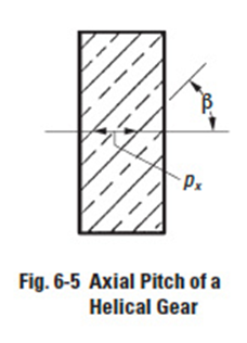
The axial pitch of a helical gear, px, is the distance between corresponding points of adjacent teeth measured parallel to the gear's axis – see Figure 6-5. Axial pitch is related to circular pitch by the expressions:
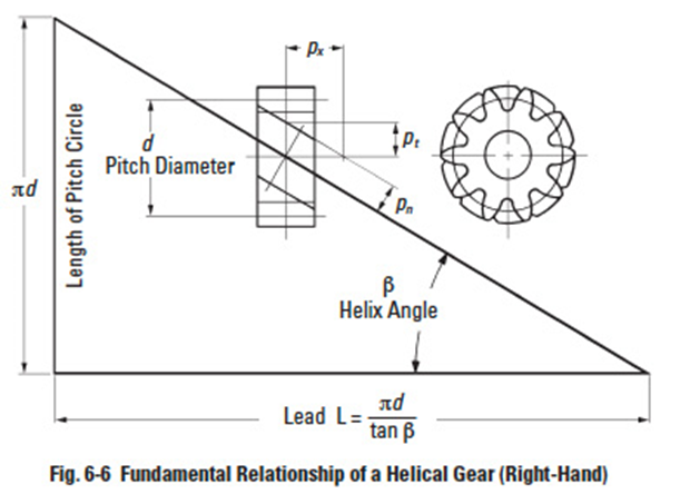
A helical gear such as shown in Figure 6-6 is a cylindrical gear in which the teeth flank are helicoid. The helix angle in standard pitch circle cylinder is β, and the displacement of one rotation is the lead, L.
The tooth profile of a helical gear is an involute curve from an axial view, or in the plane perpendicular to the axis. The helical gear has two kinds of tooth profiles – one is based on a normal system, the other is based on an axial system.
Circular pitch measured perpendicular to teeth is called normal circular pitch, pn. And pn divided by π is then a normal module, mn.
The tooth profile of a helical gear with applied normal module, mn, and normal pressure angle αn belongs to a normal system.
In the axial view, the circular pitch on the standard pitch circle is called the radial circular pitch, pt. And pt divided by π is the radial module, mt.
6.3 Equivalent Spur GearEdit
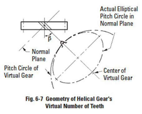
The true involute pitch and involute geometry of a helical gear is in the plane of rotation. However, in the normal plane, looking at one tooth, there is a resemblance to an involute tooth of a pitch corresponding to the normal pitch. However, the shape of the tooth corresponds to a spur gear of a larger number of teeth, the exact value depending on the magnitude of the helix angle.
The geometric basis of deriving the number of teeth in this equivalent tooth form spur gear is given in Figure 6-7. The result of the transposed geometry is an equivalent number of teeth, given as:
This equivalent number is also called a virtual number because this spur gear is imaginary. The value of this number is used in determining helical tooth strength.
6.4 Helical Gear Pressure AngleEdit
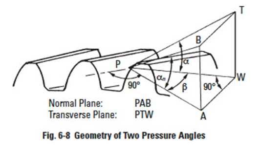
Although, strictly speaking, pressure angle exists only for a gear pair, a nominal pressure angle can be considered for an individual gear. For the helical gear there is a normal pressure, αn , angle as well as the usual pressure angle in the plane of rotation, α. Figure 6-8 shows their relationship, which is expressed as:
6.5 Importance Of Normal Plane GeometryEdit
Because of the nature of tooth generation with a rack-type hob, a single tool can generate helical gears at all helix angles as well as spur gears. However, this means the normal pitch is the common denominator, and usually is taken as a standard value. Since the true involute features are in the transverse plane, they will differ from the standard normal values. Hence, there is a real need for relating parameters in the two reference planes.
6.6 Helical Tooth ProportionsEdit
These follow the same standards as those for spur gears. Addendum, dedendum, whole depth and clearance are the same regardless of whether measured in the plane of rotation or the normal plane. Pressure angle and pitch are usually specified as standard values in the normal plane, but there are times when they are specified as standard in the transverse plane.
6.7 Parallel Shaft Helical Gear MeshesEdit
Fundamental information for the design of gear meshes is as follows:
Helix angle – Both gears of a meshed pair must have the same helix angle. However, the helix direction must be opposite; i.e., a left-hand mates with a right-hand helix.
Pitch diameter – This is given by the same expression as for spur gears, but if the normal module is involved it is a function of the helix angle. The expressions are:
Center distance – Utilizing Equation (6-7), the center distance of a helical gear mesh is:
Note that for standard parameters in the normal plane, the center distance will not be a standard value compared to standard spur gears. Further, by manipulating the helix angle, β, the center distance can be adjusted over a wide range of values. Conversely, it is possible:
- to compensate for significant center distance changes (or errors) without changing the speed ratio between parallel geared shafts; and
- to alter the speed ratio between parallel geared shafts, without changing the center distance, by manipulating the helix angle along with the numbers of teeth
6.8 Helical Gear Contact RatioEdit
The contact ratio of helical gears is enhanced by the axial overlap of the teeth. Thus, the contact ratio is the sum of the transverse contact ratio, calculated in the same manner as for spur gears, and a term involving the axial pitch.
Details of contact ratio of helical gearing are given later in a general coverage of the subject; see SECTION 11.1.
6.9 Design ConsiderationsEdit
6.9.1 Involute InterferenceEdit
Helical gears cut with standard normal pressure angles can have considerably higher pressure angles in the plane of rotation – see Equation (6-6) – depending on the helix angle.
Therefore, the minimum number of teeth without undercutting can be significantly reduced, and helical gears having very low numbers of teeth without undercutting are feasible.
6.9.2 Normal Vs. Radial Module (Pitch)Edit
In the normal system, helical gears can be cut by the same gear hob if module mn and pressure angle αn are constant, no matter what the value of helix angle β.
It is not that simple in the radial system. The gear hob design must be altered in accordance with the changing of helix angle β, even when the module mt and the pressure angle αt are the same.
Obviously, the manufacturing of helical gears is easier with the normal system than with the radial system in the plane perpendicular to the axis.
6.10 Helical Gear CalculationsEdit
6.10.1 Normal System Helical GearEdit
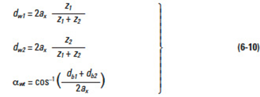
In the normal system, the calculation of a profile shifted helical gear, the working pitch diameter dw and working pressure angle αwt in the axial system is done per Equations (6-10). That is because meshing of the helical gears in the axial direction is just like spur gears and the calculation is similar.
Table 6-1 shows the calculation of profile shifted helical gears in the normal system. If normal coefficients of profile shift xn1, xn2 are zero, they become standard gears.
If center distance, ax, is given, the normal coefficient of profile shift xn1 and xn2 can be calculated from Table 6-2. These are the inverse equations from items 4 to 10 of Table 6-1.
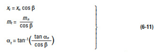
The transformation from a normal system to a radial system is accomplished by the following equations:
6.10.2 Radial System Helical GearEdit
Table 6-3 shows the calculation of profile shifted helical gears in a radial system. They become standard if xt1 = xt2 = 0.
Table 6-4 presents the inverse calculation of items 5 to 9 of Table 6-3.
The transformation from a radial to a normal system is described by the following equations:
6.10.3 Sunderland Double Helical GearEdit
A representative application of radial system is a double helical gear, or herringbone gear, made with the Sunderland machine. The radial pressure angle, αt, and helix angle, β, are specified as 20° and 22.5°, respectively. The only differences from the radial system equations of Table 6-3 are those for addendum and whole depth. Table 6-5 presents equations for a Sunderland gear.
6.10.4 Helical RackEdit
Viewed in the normal direction, the meshing of a helical rack and gear is the same as a spur gear and rack. Table 6-6 presents the calculation examples for a mated helical rack with normal module and normal pressure angle standard values. Similarly, Table 6-7 presents examples for a helical rack in the radial system (i.e., perpendicular to gear axis).
The formulas of a standard helical rack are similar to those of Table 6-6 with only the normal coefficient of profile shift xn = 0. To mesh a helical gear to a helical rack, they musthave the same helix angle but with opposite hands. The displacement of the helical rack, l, for one rotation of the mating gear is the product of the radial pitch, pt, and number of teeth.
According to the equations of Table 6-7, let radial pitch pt = 8 mm and displacement> l = 160 mm. The radial pitch and the displacement could be modified into integers, if the helix angle were chosen properly. In the axial system, the linear displacement of the helical rack, l, for one turn of the helical gear equals the integral multiple of radial pitch.
Section 7: Screw gear or crossed helical gear meshesEdit
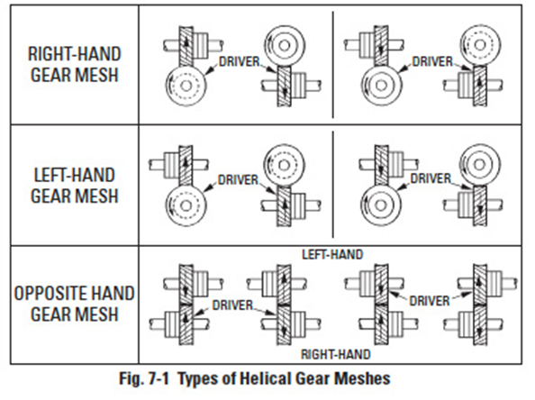
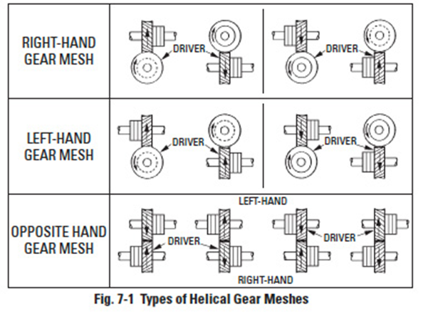
These helical gears are also known as spiral gears. They are true helical gears and only differ in their application for interconnecting skew shafts, such as in Figure 7-1. Screw gears can be designed to connect shafts at any angle, but in most applications the shafts are at right angles.
NOTES:
- Helical gears of the same hand operate at right angles.
- Helical gears of opposite hand operate on parallel shafts.
- Bearing location indicates the direction of thrust.
7.1 FeaturesEdit
7.1.1 Helix Angle And Hands The helix angles need not be the same. However, their sum must equal the shaft angle:Edit
7.1.2 ModuleEdit
Because of the possibility of different helix angles for the gear pair, the radial modules may not be the same. However, the normal modules must always be identical.
7.1.3 Center DistanceEdit
The pitch diameter of a crossed-helical gear is given by Equation (6-7), and the centre distance becomes:
Again, it is possible to adjust the center distance by manipulating the helix angle. However, helix angles of both gears must be altered consistently in accordance with Equation (7-1).
7.1.4 Velocity RatioEdit
Unlike spur and parallel shaft helical meshes, the velocity ratio (gear ratio) cannot be determined from the ratio of pitch diameters, since these can be altered by juggling of helix angles. The speed ratio can be determined only from the number of teeth, as follows:
or, if pitch diameters are introduced, the relationship is:
7.2 Screw Gear CalculationsEdit
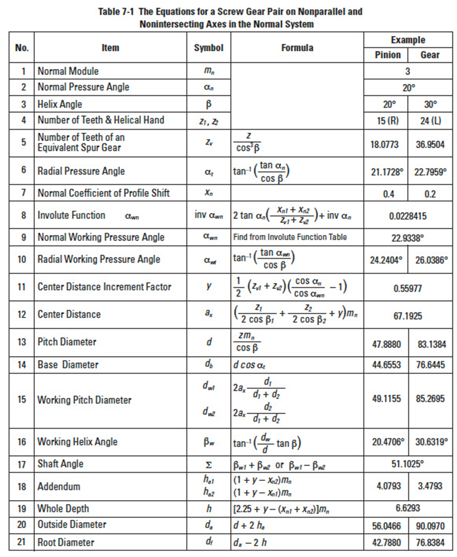
Two screw gears can only mesh together under the conditions that normal modules, mn1, and, mn2, and normal pressure angles, αn1, αn2, are the same. Let a pair of screw gears have the shaft angle Σ; and helical angles β1 and β2:
If the screw gears were profile shifted, the meshing would become a little more complex.
Let βw1, βw2 represent the working pitch cylinder;
Table 7-1 presents equations for a profile shifted screw gear pair. When the normal coefficients of profile shift xn1 = xn2 = 0, the equations and calculations are the same as for standard gears.
Standard screw gears have relations as follows:
7.3 Axial Thrust Of Helical GearsEdit
In both parallel-shaft and crossed-shaft applications, helical gears develop an axial thrust load. This is a useless force that loads gear teeth and bearings and must accordingly be considered in the housing and bearing design. In some special instrument designs, this thrust load can be utilized to actuate face clutches, provide a friction drag, or other special purpose. The magnitude of the thrust load depends on the helix angle and is given by the expression:
Where
WT= axial thrust load, and Wt = transmitted load.
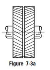
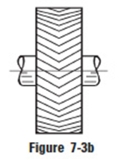
The direction of the thrust load is related to the hand of the gear and the direction of rotation. This is depicted in Figure 7-1. When the helix angle is larger than about 20°, the use of double helical gears with opposite hands (Figure 7-3a) or herringbone gears () is worth considering.
More detail on thrust force of helical gears is presented in SECTION 16.
Section 8: bevel gearingEdit
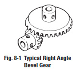
For intersecting shafts, bevel gears offer a good means of transmitting motion and power. Most transmissions occur at right angles, Figure 8-1, but the shaft angle can be any value. Ratios up to 4:1 are common, although higher ratios are possible as well.
8.1 Development And Geometry Of Bevel GearsEdit
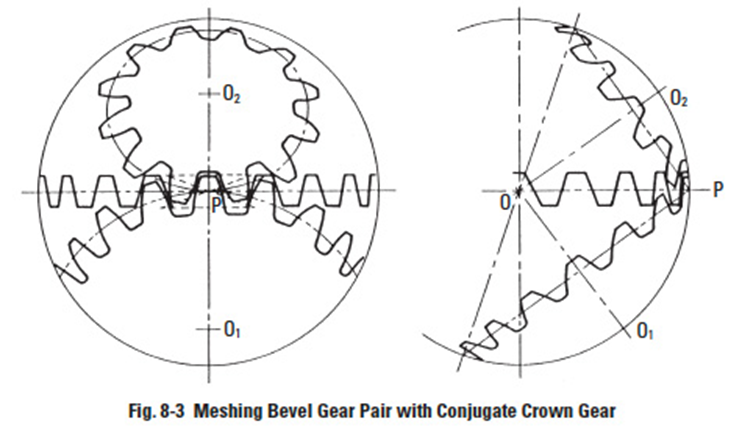
Bevel gears have tapered elements because they are generated and operate, in theory, on the surface of a sphere. Pitch diameters of mating bevel gears belong to frusta of cones, as shown in Figure 8-2a. In the full development on the surface of a sphere, a pair of meshed bevel gears are in conjugate engagement as shown in Figure 8-2b.
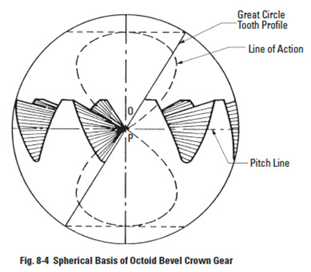
The crown gear, which is a bevel gear having the largest possible pitch angle (defined in Figure 8-3), is analogous to the rack of spur gearing, and is the basic tool for generating bevel gears. However, for practical reasons, the tooth form is not that of a spherical involute, and instead, the crown gear profile assumes a slightly simplified form. Although the deviation from a true spherical involute is minor, it results in a line-of-action having a figure-8 trace in its extreme extension; see Figure 8-4. This shape gives rise to the name "octoid" for the tooth form of modern bevel gears.
8.2 Bevel Gear Tooth ProportionsEdit
Bevel gear teeth are proportioned in accordance with the standard system of tooth proportions used for spur gears. However, the pressure angle of all standard design bevel gears is limited to 20°. Pinions with a small number of teeth are enlarged automatically when the design follows the Gleason system.
Since bevel-tooth elements are tapered, tooth dimensions and pitch diameter are referenced to the outer end (heel). Since the narrow end of the teeth (toe) vanishes at the pitch apex (center of reference generating sphere), there is a practical limit to the length (face) of a bevel gear. The geometry and identification of bevel gear parts is given in Figure 8-5.
8.3 Velocity RatioEdit
The velocity ratio, i, can be derived from the ratio of several parameters:
where: δ = pitch angle (see Figure 8-5)
8.4 Forms Of Bevel TeethEdit
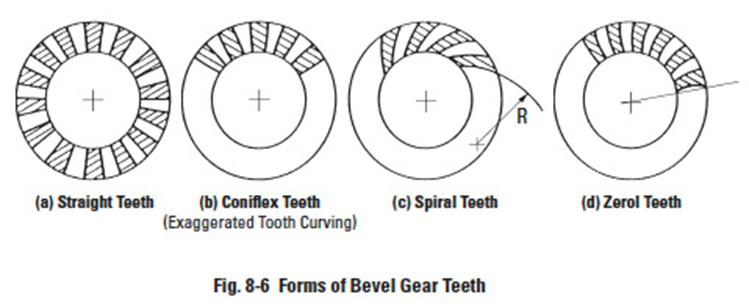
In the simplest design, the tooth elements are straight radial, converging at the cone apex. However, it is possible to have the teeth curve along a spiral as they converge on the cone apex, resulting in greater tooth overlap, analogous to the overlapping action of helical teeth. The result is a spiral bevel tooth. In addition, there are other possible variations. One is the zerol bevel, which is a curved tooth having elements that start and end on the same radial line.
Straight bevel gears come in two variations depending upon the fabrication equipment. All current Gleason straight bevel generators are of the Coniflex form which gives an almost imperceptible convexity to the tooth surfaces. Older machines produce true straight elements. See Figure 8-6a.
Straight bevel gears are the simplest and most widely used type of bevel gears for the transmission of power and/or motion between intersecting shafts. Straight bevel gears are recommended:
- When speeds are less than 300 meters/min (1000 feet/min) – at higher speeds, straight bevel gears may be noisy.
- When loads are light, or for high static loads when surface wear is not a critical factor.
- When space, gear weight, and mountings are a premium. This includes planetary gear sets, where space does not permit the inclusion of rolling-element bearings.
Other forms of bevel gearing include the following:
Coniflex gears (Figure 8-6b) are produced by current Gleason straight bevel gear generating machines that crown the sides of the teeth in their lengthwise direction. The teeth, therefore, tolerate small amounts of misalignment in the assembly of the gears and some displacement of the gears under load without concentrating the tooth contact at the ends of the teeth. Thus, for the operating conditions, Coniflex gears are capable of transmitting larger loads than the predecessor Gleason straight bevel gears.
Spiral bevels (Figure 8-6c) have curved oblique teeth which contact each other gradually and smoothly from one end to the other. Imagine cutting a straight bevel into an infinite number of short face width sections, angularly displace one relative to the other, and one has a spiral bevel gear. Well-designed spiral bevels have two or more teeth in contact at all times. The overlapping tooth action transmits motion more smoothly and quietly than with straight bevel gears.
Zerol bevels (Figure 8-6d) have curved teeth similar to those of the spiral bevels, but with zero spiral angle at the middle of the face width; and they have little end thrust. Both spiral and Zerol gears can be cut on the same machines with the same circular face-mill cutters or ground on the same grinding machines. Both are produced with localized tooth contact which can be controlled for length, width, and shape.
Functionally, however, Zerol bevels are similar to the straight bevels and thus carry the same ratings. In fact, Zerols can be used in the place of straight bevels without mounting changes.
Zerol bevels are widely employed in the aircraft industry, where ground-tooth precision gears are generally required. Most hypoid cutting machines can cut spiral bevel, Zerol or hypoid gears.
8.5 Bevel Gear CalculationsEdit
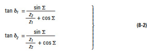
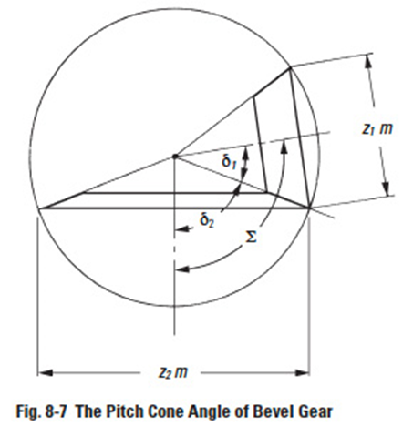
Let z'1 and z'2 be pinion and gear tooth numbers; shaft angle Σ and pitch cone angles δ1 and δ2; then:
Generally, shaft angle Σ = 90° is most used. Other angles (Figure 8-7) are sometimes used. Then, it is called "bevel gear in nonright angle drive". The 90° case is called "bevel gear in right angle drive".
When Σ = 90°, Equation (8-2) becomes:
Miter gears are bevel gears with Σ = 90° and z'1 = z'2. Their speed ratio z'1 / z'2 = 1. They only change the direction of the shaft, but do not change the speed.
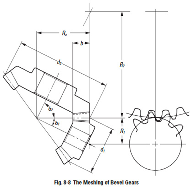
Figure 8-8 depicts the meshing of bevel gears. The meshing must be considered in pairs. It is because the pitch cone angles δ1 and δ2 are restricted by the gear ratio z'1 / z'2. In the facial view, which is normal to the contact line of pitch cones, the meshing of bevel gears appears to be similar to the meshing of spur gears.
8.5.1 Gleason Straight Bevel GearsEdit
The straight bevel gear has straight teeth flanks which are along the surface of the pitch cone from the bottom to the apex. Straight bevel gears can be grouped into the Gleason type and the standard type.
In this section, we discuss the Gleason straight bevel gear. The Gleason Company defined the tooth profile as: whole depth h = 2.188 m; top clearance c'a = 0.188 m; and working depth h'w = 2.000 m.
The characteristics are:
Design specified profile shifted gears:
In the Gleason system, the pinion is positive shifted and the gear is negative shifted. The reason is to distribute the proper strength between the two gears. Miter gears, thus, do not need any shifted tooth profile.
The top clearance is designed to be parallel
The outer cone elements of two paired bevel gears are parallel. That is to ensure that the top clearance along the whole tooth is the same. For the standard bevel gears, top clearance is variable. It is smaller at the toe and bigger at the heel.
Table 8-1 shows the minimum number of teeth to prevent undercut in the Gleason system at the shaft angle Σ = 90°.
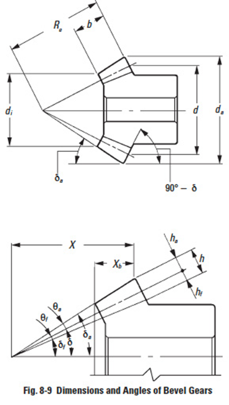
Table 8-2 presents equations for designing straight bevel gears in the Gleason system. The meanings of the dimensions and angles are shown in Figure 8-9. All the equations in Table 8-2 can also be applied to bevel gears with any shaft angle.
The straight bevel gear with crowning in the Gleason system is called a Coniflex gear. It is manufactured by a special Gleason "Coniflex" machine. It can successfully eliminate poor tooth wear due to improper mounting and assembly.
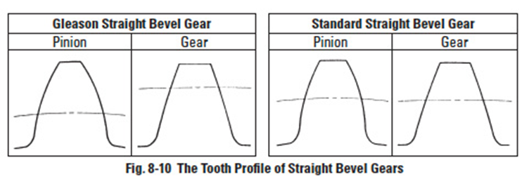
The first characteristic of a Gleason straight bevel gear is its profile shifted tooth. From Figure 8-10, we can see the positive tooth profile shift in the pinion. The tooth thickness at the root diameter of a Gleason pinion is larger than that of a standard straight bevel gear.
8.5.2. Standard Straight Bevel GearsEdit
A bevel gear with no profile shifted tooth is a standard straight bevel gear. The applicable equations are in Table 8-3.
These equations can also be applied to bevel gear sets with other than 90° shaft angle.
8.5.3 Gleason Spiral Bevel GearsEdit
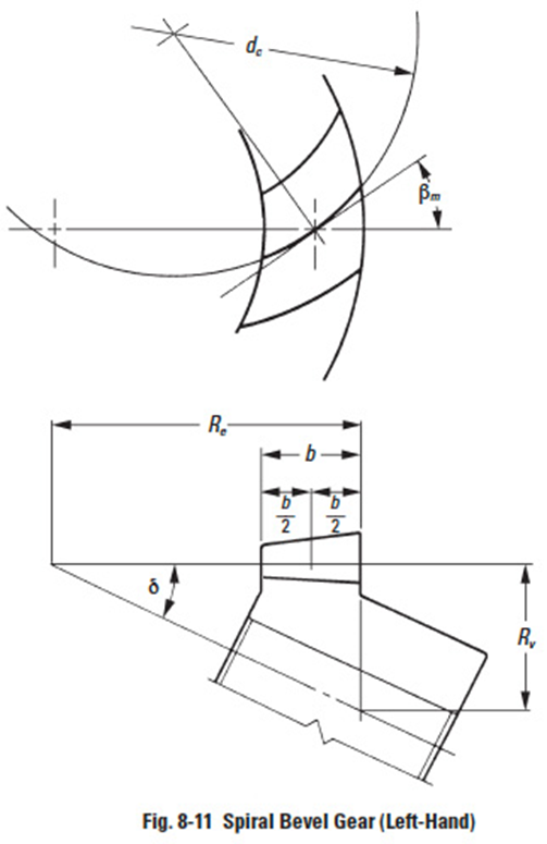
A spiral bevel gear is one with a spiral tooth flank as in Figure 8-11. The spiral is generally consistent with the curve of a cutter with the diameter d'c. The spiral angle β is the angle between a generatrix element of the pitch cone and the tooth flank. The spiral angle just at the tooth flank center is called central spiral angle βm . In practice, spiral angle means central spiral angle.
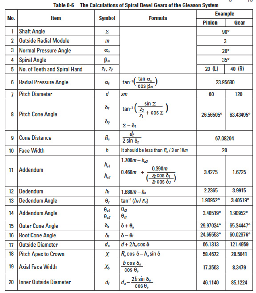
All equations in Table 8-6 are dedicated for the manufacturing method of Spread Blade or of Single Side from Gleason. If a gear is not cut per the Gleason system, the equations will be different from these.
The tooth profile of a Gleason spiral bevel gear shown here has the whole depth h = 1.888 m; top clearance c'a = 0.188m; and working depth h'w = 1.700m. These Gleason spiral bevel gears belong to a stub gear system. This is applicable to gears with modules m > 2.1.
Table 8-4 shows the minimum number of teeth to avoid undercut in the Gleason system with shaft angle Σ = 90° and pressure angle α'n = 20°.
If the number of teeth is less than 12, Table 8-5 is used to determine the gear sizes.
All equations in Table 8-6 are also applicable to Gleason bevel gears with any shaft angle. A spiral bevel gear set requires matching of hands; left-hand and right-hand as a pair.
8.5.4 Gleason Zerol Spiral Bevel GearsEdit
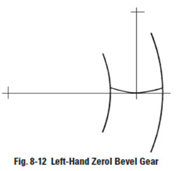
When the spiral angle βm = 0, the bevel gear is called a Zerol bevel gear. The calculation equations of Table 8-2 for Gleason straight bevel gears are applicable. They also should take care again of the rule of hands; left and right of a pair must be matched. Figure 8-12 is a left-hand Zerol bevel gear.
