Gears sections 17 - 21
Section 17: Strength and durability of gearsEdit
The strength of gears is generally expressed in terms of bending strength and surface durability. These are independent criteria which can have differing criticalness, although usually both are important.
Discussions in this section are based upon equations published in the literature of the Japanese Gear Manufacturer Association (JGMA). Reference is made to the following JGMA specifications:
Specifications of JGMA:
JGMA 401-01: Bending Strength Formula of Spur Gears and Helical Gears
JGMA 402-01: Bending Strength Formula of Bevel Gears
JGMA 404-01: Surface Durability Formula of Bevel Gears
JGMA 405-01: The Strength Formula of Worm Gears
Generally, bending strength and durability specifications are applied to spur and helical gears (including double helical and internal gears) used in industrial machines in the following range:
Module: m, 1.5 to 25 mm
Pitch Diameter: d, 25 to 3200 mm
Tangential Speed: v, less than 25 m/sec
Rotating Speed: n, less than 3600 rpm
Conversion Formulas: Power, Torque and Force
Gear strength and durability relate to the power and forces to be transmitted. Thus, the equations that relate tangential force at the pitch circle, Ft (kgf), power, P (kw), and torque, T (kgf • m) are basic to the calculations. The relations are as follows:
17.1 Bending Strength Of Spur And Helical GearsEdit
In order to confirm an acceptable safe bending strength, it is necessary to analyze the applied tangential force at the working pitch circle, Ft, vs. allowable force, Ft lim. This is stated as:
It should be noted that the greatest bending stress is at the root of the flank or base of the dedendum. Thus, it can be stated:
σF = actual stress on dedendum at root
σF lim = allowable stress
Then Equation (17-4) becomes Equation (17-5)
Equation (17-6) presents the calculation of Ft lim:
Equation (17-6) can be converted into stress by Equation (17-7):
17.1.1 Determination of Factors in the Bending Strength EquationEdit
If the gears in a pair have different blank widths, let the wider one be bw and the narrower one be bs.
And if:
bw – bs ≤ mn, bw and bs can be put directly into Equation (17-6).
bw – bs > mn, the wider one would be changed to bs + mn and the narrower one, bs, would be unchanged.
17.1.2 Tooth Profile Factor, YFEdit
The factor YF is obtainable from Figure 17-1 based on the equivalent number of teeth, zv, and coefficient of profile shift, x, if the gear has a standard tooth profile with 20° pressure angle, per JIS B 1701. The theoretical limit of undercut is shown. Also, for profile shifted gears the limit of too narrow (sharp) a tooth top land is given. For internal gears, obtain the factor by considering the equivalent racks.
17.1.3 Load Distribution Factor,Yε
Load distribution factor is the reciprocal of radial contact ratio.
Figure 17-1
Table 17-1
Table 17-1 shows the radial contact ratio of a standard spur gear.
17.1.4 Helix Angle Factor, YβEdit
Helix angle factor can be obtained from Equation (17-9).
=
Table 17-2
17.1.5 Life Factor, KL
We can choose the proper life factor, KL, from Table 17-2. The number of cyclic repetitions means the total loaded meshings during its lifetime.
17.1.6 Dimension Factor of Root Stress, KFXEdit
Generally, this factor is unity.
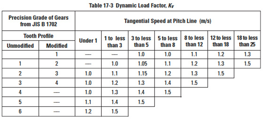
Table 17-3
17.1.7 Dynamic Load Factor, KVEdit
Dynamic load factor can be obtained from Table 17-3 based on the precision of the gear and its pitch line linear speed.
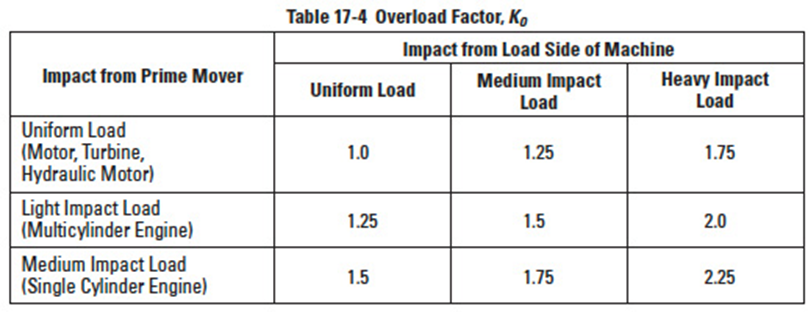
Table 17-4
17.1.8 Overload Factor, K0Edit
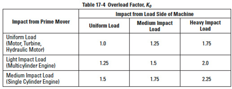
Overload factor, K0, is the quotient of actual tangential force divided by nominal tangential force, Ft. If tangential force is unknown, Table 17-4 provides guiding values.
17.1.9 Safety Factor for Bending Failure, SFEdit
Safety factor, SF, is too complicated to be decided precisely. Usually, it is set to at least 1.2.
Table 17-5
Table 17-6
Table 17-7
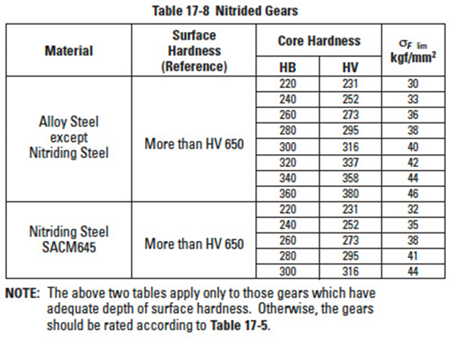
Table 17-8
Table 17-8A
Table 17-8B
17.1.10 Allowable Bending Stress At Root, δF limEdit
For the unidirectionally loaded gear, the allowable bending stresses at the root are shown in Tables 17-5 to 17-8. In these tables, the value of δF lim is the quotient of the tensile fatigue limit divided by the stress concentration factor 1.4. If the load is bidirectional, and both sides of the tooth are equally loaded, the value of allowable bending stress should be taken as 2/3 of the given value in the table. The core hardness means hardness at the center region of the root.
See Table 17-5 for δF lim of gears without case hardening. Table 17-6 gives δF lim of gears that are induction hardened; and Tables 17-7 and 17-8 give the values for carburized and nitrided gears, respectively. In Tables 17-8A and 17-8B, examples of calculations are given.
17.2 Surface Strength Of Spur And Helical GearsEdit
The following equations can be applied to both spur and helical gears, including double helical and internal gears, used in power transmission. The general range of application is:
Module: m, 1.5 to 25 mm
Pitch Circle: d, 25 to 3200 mm
Linear Speed: v, less than 25 m/sec
Rotating Speed: n, less than 3600 rpm
17.2.1 Conversion FormulasEdit
To rate gears, the required transmitted power and torques must be converted to tooth forces. The same conversion formulas, Equations (17-1), (17-2) and (17-3), of SECTION 17 are applicable to surface strength calculations.
17.2.2 Surface Strength EquationsEdit
As stated in SECTION 17.1, the tangential force, Ft, is not to exceed the allowable tangential force, Ft lim. The same is true for the allowable Hertz surface stress, σH lim. The Hertz stress σH is calculated from the tangential force, Ft. For an acceptable design, it must be less than the allowable Hertz stress σH lim. That is:
The tangential force, σH lim, in kgf, at the standard pitch circle, can be calculated from Equation (17-13).
The Hertz stress σH (kgf/mm²) is calculated from Equation (17-14), where u is the ratio of numbers of teeth in the gear pair.
The "+" symbol in Equations (17-13) and (17-14) applies to two external gears in mesh, whereas the "–" symbol is used for an internal gear and an external gear mesh. For the case of a rack and gear, the quantity u/(u ± 1) becomes 1.
17.2.3 Determination Of Factors In The Surface Strength EquationsEdit
17.2.3.A Effective Tooth Width, bH (mm)Edit
The narrower face width of the meshed gear pair is assumed to be the effective width for surface strength. However, if there are tooth modifications, such as chamfer, tip relief or crowning, an appropriate amount should be subtracted to obtain the effective tooth width.
17.2.3.B Zone Factor, ZHEdit
The zone factor is defined as:
where: βb = tan-1 (tan β cos αt) Figure 17-2
The zone factors are presented in Figure 17-2 for tooth profiles per JIS B 1701, specified in terms of profile shift coefficients x1 and x2, numbers of teeth z1 and z2 and helix angle β.
The "+" symbol in Figure 17-2 applies to external gear meshes, whereas the "–" is used for internal gear and external gear meshes.
17.2.3.C Material Factor, ZM
where:
Table 17-9
ν = Poisson's Ratio, and E = Young's Modulus
Table 17-9 contains several combinations of material and their material factor.
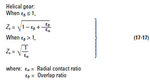
17.2.4 Contact Ratio Factor, ZεEdit
This factor is fixed at 1.0 for spur gears.
For helical gear meshes, Zε is calculated as follows:
17.2.5 Helix Angle Factor, ZβEdit
Edit
This is a difficult parameter to evaluate. Therefore, it is assumed to be 1.0 unless better information is available.
17.2.6 Life Factor, KHLEdit
Table 17-10
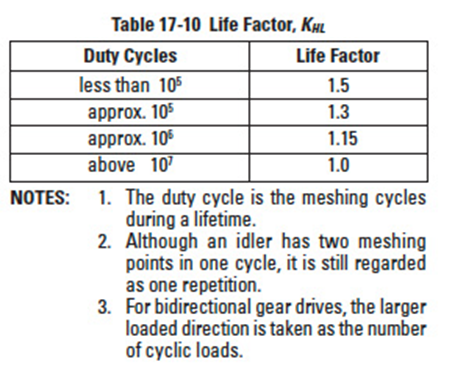
This factor reflects the number of repetitious stress cycles. Generally, it is taken as 1.0. Also, when the number of cycles is unknown, it is assumed to be 1.0. When the number of stress cycles is below 10 million, the values of Table 17-10 can be applied.
Figure 17-3
17.2.7 Lubricant Factor, ZLEdit
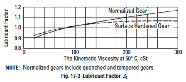
The lubricant factor is based upon the lubricant's kinematic viscosity at 50°C. See Figure 17-3.
Figure 17-4
17.2.8 Surface Roughness Factor, ZREdit
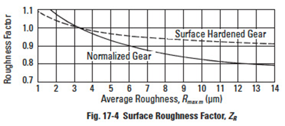
This factor is obtained from Figure 17-4 on the basis of the average roughness Rmaxm (µm). The average roughness is calculated by Equation (17-19) using the surface roughness values of the pinion and gear, Rmax1 and Rmax2, and the center distance, a, in mm.
Figure 17-5
17.2.9 Sliding Speed Factor, ZVEdit
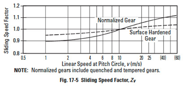
This factor relates to the linear speed of the pitch line. See Figure 17-5.
17.2.10 Hardness Ratio Factor, ZWEdit
The hardness ratio factor applies only to the gear that is in mesh with a pinion which is quenched and ground. The ratio is calculated by Equation (17-20).
where: HB2 = Brinell hardness of gear range: 130 ≤ HB2 ≤ 470
If a gear is out of this range, the ZW is assumed to be 1.0.
17.2.11 Dimension Factor, KHXEdit
Because the conditions affecting this parameter are often unknown, the factor is usually set at 1.0.
Table 17-11
17.2.12 Tooth Flank Load Distribution Factor, KH βEdit
(a) When tooth contact under load is not predictable: This case relates the ratio of the gear face width to the pitch diameter, the shaft bearing mounting positions, and the shaft sturdiness. See Table 17-11. This attempts to take into account the case where the tooth contact under load is not good or known.
(b) When tooth contact under load is good: In this case, the shafts are rugged and the bearings are in good close proximity to the gears, resulting in good contact over the full width and working depth of the tooth flanks. Then the factor is in a narrow range, as specified below:
17.2.13 Dynamic Load Factor, KVEdit
Dynamic load factor is obtainable from Table 17-3 according to the gear's precision grade and pitch line linear speed. Table 17-3
Table 17-4
Table 17-12
Table 17-12-2
Table 17-13
Table 17-14
Table 17-14A
Table 17-15
Table 17-16
Table 17-16A
Table 17-16B
Figure 17-6
17.2.14 Overload Factor, KoEdit
The overload factor is obtained from either Equation (17-11) or from Table 17-4.
17.2.15 Safety Factor For Pitting,SHEdit
The causes of pitting involves many environmental factors and usually is difficult to precisely define. Therefore, it is advised that a factor of at least 1.15 be used.
17.2.16 Allowable Hertz Stress, σH limEdit
The values of allowable Hertz stress for various gear materials are listed in Tables 17-12, 17-2 part 2, 17-13, 17-14, 17-14A, 17-15, 17-16, 17-16A and 17-16B. Values for hardness not listed can be estimated by interpolation. Surface hardness is defined as hardness in the pitch circle region. Also see Figure 17-6.
17.3 Bending Strength Of Bevel GearsEdit
This information is valid for bevel gears which are used in power transmission in general industrial machines. The applicable ranges are:
Module: m, 1.5 to 25 mm
Pitch Diameter: d, less than 1600 mm for straight bevel gears, less than 1000 mm for spiral bevel gears
Linear Speed: v, less than 25 m/sec
Rotating Speed: n, less than 3600 rpm
17.3.1 Conversion FormulasEdit
In calculating strength, tangential force at the pitch circle, Ftm, in kgf; power, P, in kW, and torque, T, in kgf • m, are the design criteria. Their basic relationships are expressed in Equations (17-23) through (17-25).
17.3.2 Bending Strength EquationsEdit
The tangential force, Ftm, acting at the central pitch circle should be equal to or less than the allowable tangential force, Ftm lim, which is based upon the allowable bending stress σF lim. That is:
The bending stress at the root, σF, which is derived from Ftm should be equal to or less than the allowable bending stress σF lim.
The tangential force at the central pitch circle, Ftm lim (kgf), is obtained from Equation (17-28).
where: βm : Central spiral angle (degrees)
m : Radial module (mm)
Ra : Cone distance (mm)
And the bending strength σF (kgf/mm2) at the root of tooth is calculated from Equation (17-29).
17.3.3 Determination of Factors in Bending Strength EquationsEdit
17.3.3.A Tooth Width, b (mm)Edit
The term b is defined as the tooth width on the pitch cone, analogous to face width of spur or helical gears. For the meshed pair, the narrower one is used for strength calculations.
Figure 17-7
Figure 17-8
Figure 17-9
17.3.3.B Tooth Profile Factor, YFEdit
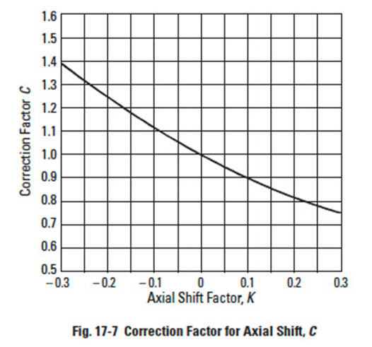
The tooth profile factor is a function of profile shift, in both the radial and axial directions. Using the equivalent (virtual) spur gear tooth number, the first step is to determine the radial tooth profile factor, YFO, from Figure 17-8 for straight bevel gears and Figure 17-9 for spiral bevel gears. Next, determine the axial shift factor, K, with Equation (17-33) from which the axial shift correction factor, C, can be obtained using Figure 17-7. Finally, calculate YF by Equation (17-30).
Should the bevel gear pair not have any axial shift, then the coefficient C is 1, as per Figure 17-7. The tooth profile factor, YF, per Equation (17-31) is simply the YFO. This value is from Figure 17-8 or 17-9, depending upon whether it is a straight or spiral bevel gear pair. The graph entry parameter values are per Equation (17-32).
where: ha = Addendum at outer end (mm)
ha0 = Addendum of standard form (mm)
m = Radial module (mm)
The axial shift factor, K, is computed from the formula:
17.3.3.C Load Distribution Factor, YεEdit
Load distribution factor is the reciprocal of radial contact ratio.
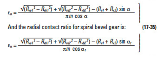
The radial contact ratio for a straight bevel gear mesh is:
Table 17-17
Table 17-18
Table 17-19
See Tables 17-17, 17-18 and 17-19 for some calculating examples of radial contact ratio for various bevel gear pairs.
17.3.3.D Spiral Angle Factor, YβEdit
The spiral angle factor is a function of the spiral angle. The value is arbitrarily set by the following conditions:
Table 17-20
Table 17-2
17.3.3.E Cutter Diameter Effect Factor, YCEdit
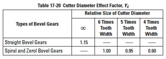
This factor of cutter diameter, YC, can be obtained from Table 17-20 by the value of tooth flank length, b / cos βm (mm), over cutter diameter. If cutter diameter is not known, assume YC = 1.00.
17.3.3.F Life Factor, KLEdit
We can choose a proper life factor, KL, from Table 17-2 similarly to calculating the bending strength of spur and helical gears.
Table 17-21
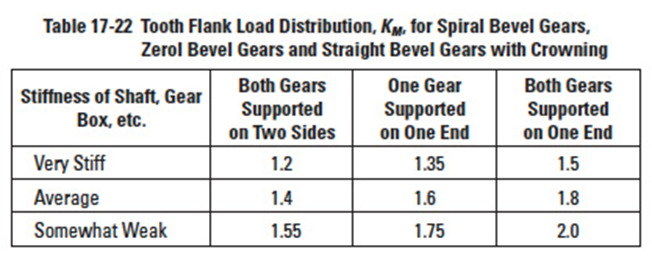
Table 17-22
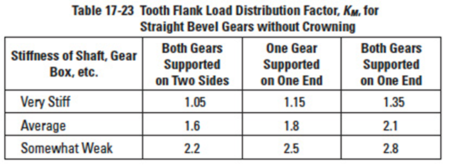
Table 17-23
17.3.3.G Dimension Factor Of Root Bending Stress, KFXEdit
This is a size factor that is a function of the radial module, m. Refer to Table 17-21 for values.
17.3.3.H Tooth Flank Load Distribution Factor, KMEdit
Tooth flank load distribution factor, KM, is obtained from Table 17-22 or Table 17-23.
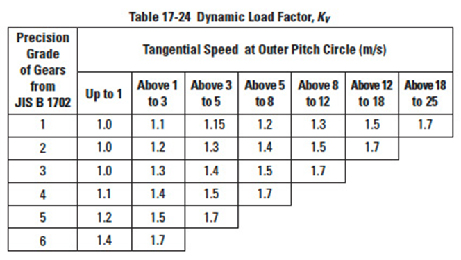
Table 17-24
Table 17-24A
Table 17-24B
17.3.3.I Dynamic Load Factor, KVEdit
Dynamic load factor, KV, is a function of the precision grade of the gear and the tangential speed at the outer pitch circle, as shown in Table 17-24. Also see Table 17-24A and Table 17-24B.
17.3.3.K Reliability Factor, KREdit
The reliability factor should be assumed to be as follows:
- General case: KR = 1.2
- When all other factors can be determined accurately: KR = 1.0
- When all or some of the factors cannot be known with certainty: KR = 1.4
Table 17-5
Table 17-8
17.3.3.L Allowable Bending Stress at Root, σF limEdit
The allowable stress at root σF lim can be obtained from Tables 17-5 through 17-8, similar to the case of spur and helical gears.
17.4 Surface Strength Of Bevel GearsEdit
This information is valid for bevel gears which are used in power transmission in general industrial machines. The applicable ranges are:
Radial Module: m, 1.5 to 25 mm
Pitch Diameter: d, Straight bevel gear under 1600 mm
Spiral bevel gear under 1000 mm
Linear Speed: v, less than 25 m/sec
Rotating Speed: n, less than 3600 rpm
17.4.1 Basic Conversion FormulasEdit
The same formulas of SECTION 17.3 apply.
17.4.2 Surface Strength EquationsEdit
In order to obtain a proper surface strength, the tangential force at the central pitch circle, Ftm, must remain below the allowable tangential force at the central pitch circle, Ftm lim, based on the allowable Hertz stress σF lim.
Alternately, the Hertz stress σH, which is derived from the tangential force at the central pitch circle must be smaller than the allowable Hertz stress σH lim.
The allowable tangential force at the central pitch circle, Ftm lim, in kgf can be calculated from Equation (17-39).
The Hertz stress, σH (kgf/mm2) is calculated from Equation (17-40).
17.4.3 Determination of Factors In Surface Strength EquationsEdit
17.4.3.A Tooth Width, b (mm)Edit
This term is defined as the tooth width on the pitch cone. For a meshed pair, the narrower gear's "b" is used for strength calculations.
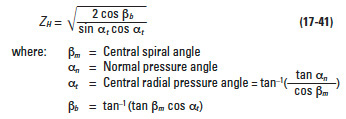
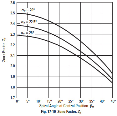
17.4.3.B Zone Factor, ZHEdit
The zone factor is defined as:
Figure 17-10
If the normal pressure angle αn is 20°, 22.5° or 25°, the zone factor can be obtained from Figure 17-10.
17.4.3.C Material Factor, ZMEdit
The material factor, ZM, is obtainable from Table 17-9.
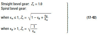
17.4.3.D Contact Ratio Factor, ZεEdit
The contact ratio factor is calculated from the equations below.
where: εα = Radial Contact Ratio
εβ = Overlap Ratio
17.4.3.E Spiral Angle Factor, ZβEdit
Little is known about these factors, so usually it is assumed to be unity.
Figure 17-11
17.4.3.F Life Factor, KHLEdit
The life factor for surface strength is obtainable from Table 17-10.
17.4.3.G Lubricant Factor, ZLEdit
The lubricant factor, ZL, is found in Figure 17-3.
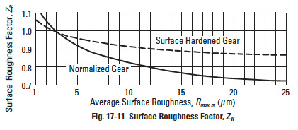
17.4.3.H Surface Roughness Factor, ZREdit
The surface roughness factor is obtainable from Figure 17-11 on the basis of average roughness, Rmaxm, in µ m. The average surface roughness is calculated by Equation (17-44) from the surface roughnesses of the pinion and gear (Rmaxm1 and Rmaxm2), and the center distance, a, in mm.
17.4.3.I Sliding Speed Factor, ZVEdit
The sliding speed factor is obtained from Figure 17-5 based on the pitch circle linear speed.
17.4.3.J Hardness Ratio Factor, ZWEdit
The hardness ratio factor applies only to the gear that is in mesh with a pinion which is quenched and ground. The ratio is calculated by Equation (17-45).
where Brinell hardness of the gear is: 130 ≤ HB2 ≤ 470
If the gear's hardness is outside of this range, ZW is assumed to be unity.
17.4.3.K Dimension Factor, KHXEdit
Since, often, little is known about this factor, it is assumed to be unity.
Table 17-25
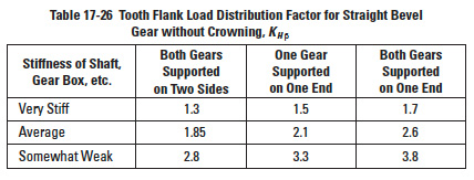
Table 17-26
Table 17-26A
Table 17-26B
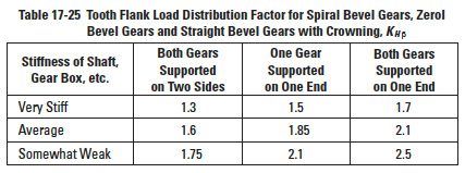
17.4.3.L Tooth Flank Load Distribution Factor, KH βEdit
Factors are listed in Tables 17-25 and 17-26. If the gear and pinion are unhardened, the factors are to be reduced to 90% of the values in the table. Also see Tables 17-26A and 17-26B.
17.4.3.M Dynamic Load Factor, KVEdit
The dynamic load factor can be obtained from Table 17-24.
17.4.3.N Overload Factor, K0Edit
The overload factor can be computed by Equation 17-11 or found in Table 17-4.
17.4.3.O Reliability Factor, CREdit
The general practice is to assume CR to be at least 1.15. 17.4.3.P Allowable Hertz Stress, σH lim
The values of allowable Hertz stress are given in Tables 17-12 through 17-16.
17.5 Strength Of Worm GearingEdit
This information is applicable for worm gear drives that are used to transmit power in general industrial machines with the following parameters:
Axial Module: mx, 1 to 25 mm
Pitch Diameter of Worm Gear: d2, less than 900 mm
Sliding Speed: vs, less than 30 m/sec
Rotating Speed, Worm Gear: n2, less than 600 rpm
17.5.1 Basic Formulas:Edit
17.5.2 Torque, Tangential Force and EfficiencyEdit
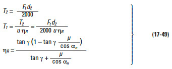
(1) Worm as Driver Gear (Speed Reducing)
where:
T2 = Nominal torque of worm gear (kg • m)
T1 = Nominal torque of worm (kgf • m)
Ft = Nominal tangential force on worm gear's pitch circle (kgf)
d2 = Pitch diameter of worm gear (mm)
u = Teeth number ratio = z2 /zw
ηR = Transmission efficiency, worm driving (not including bearing loss, lubricant agitation loss, etc.)
µ= Friction coefficient
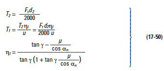
(2) Worm Gear as Driver Gear (Speed Increasing)
where: ηI = Transmission efficiency, worm gear driving (not including bearing loss, lubricant agitation loss, etc.)
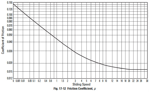
Figure 17-12
Table 17-27
17.5.3 Friction Coefficient, µEdit
The friction factor varies as sliding speed changes. The combination of materials is important. For the case of a worm that is carburized and ground, and mated with a phosphorous bronze worm gear, see Figure 17-12. For some other materials, see Table 17-27.
For lack of data, friction coefficient of materials not listed in Table 17-27 are very difficult to obtain. H.E. Merritt has offered some further information on this topic. See Reference 9.
17.5.4 Surface Strength of Worm Gearing MeshEdit
(1) Calculation of Basic Load
Provided dimensions and materials of the worm pair are known, the allowable load is as follows:
(2) Calculation of Equivalent Load
The basic load Equations (17-51) and (17-52) are applicable under the conditions of no impact and the pair can operate for 26000 hours minimum. The condition of "no impact" is defined as the starting torque which must be less than 200% of the rated torque; and the frequency of starting should be less than twice per hour.
An equivalent load is needed to compare with the basic load in order to determine an actual design load, when the conditions deviate from the above.
Equivalent load is then converted to an equivalent tangential force, Fte, in kgf:
and equivalent worm gear torque, T2e, in kgf • m:
(3) Determination of Load
Under no impact condition, to have life expectancy of 26000 hours, the following relationships must be satisfied:
For all other conditions:
NOTE: If load is variable, the maximum load should be used as the criterion.
17.5.5 Determination of Factors in Worm Gear Surface Strength EquationsEdit
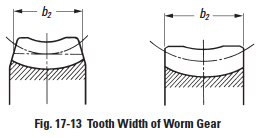
17.5.5.A Tooth Width of Worm Gear, b2 (mm)Edit
Tooth width of worm gear is defined as in Figure 17-13.
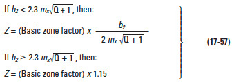
17.5.5.B Zone Factor, ZEdit
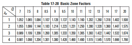
Table 17-28
where: Basic Zone Factor is obtained from Table 17-28.
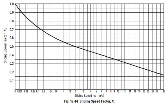
Figure 17-14
17.5.5.C Sliding Speed Factor, KvEdit
The sliding speed factor is obtainable from Figure 17-14, where the abscissa is the pitch line linear velocity.
Figure 17-15
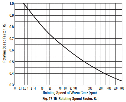
17.5.5.D Rotating Speed Factor, KnEdit
The rotating speed factor is presented in Figure 17-15 as a function of the worm gear's rotating speed, n2.
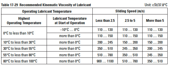
Table 17-29
17.5.5.E Lubricant Factor, ZLEdit
Let ZL = 1.0 if the lubricant is of proper viscosity and has antiscoring additives. Some bearings in worm gear boxes may need a low viscosity lubricant. Then ZL is to be less than 1.0. The recommended kinetic viscosity of lubricant is given in Table 17-29.
Table 17-30
17.5.5.F Lubrication Factor, ZMEdit
The lubrication factor, ZM, is obtained from Table 17-30.
17.5.5.G Surface Roughness Factor, ZREdit
This factor is concerned with resistance to pitting of the working surfaces of the teeth. Since there is insufficient knowledge about this phenomenon, the factor is assumed to be 1.0.
It should be noted that for Equation (17-58) to be applicable, surfaces roughness of the worm and worm gear must be less than 3 µm and 12 µm respectively. If either is rougher, the factor is to be adjusted to a smaller value.
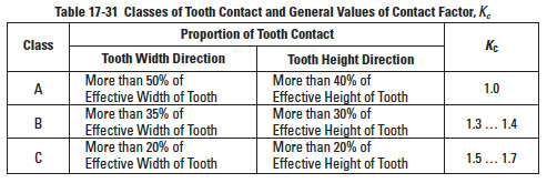
17.5.5.H Contact Factor, KcEdit
Quality of tooth contact will affect load capacity dramatically. Generally, it is difficult to define precisely, but JIS B 1741 offers guidelines depending on the class of tooth contact.
Table 17-31
Table 17-31 gives the general values of Kc depending on the JIS tooth contact class.
Table 17-32
17.5.5.I Starting Factor, KsEdit
This factor depends upon the magnitude of starting torque and the frequency of starts. When starting torque is less than 200% of rated torque, Ks factor is per Table 17-32.
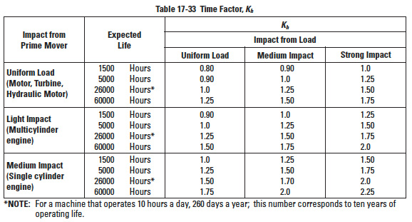
Table 17-33
17.5.5.J Time Factor, KhEdit
This factor is a function of the desired life and the impact environment. See Table 17-33. The expected lives in between the numbers shown in Table 17-33 can be interpolated.
Table 17-34
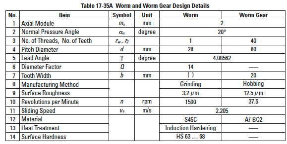
Table 17-35A
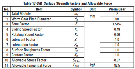
Table 17-35B
17.5.5.K Allowable Stress Factor, Sc limEdit
Table 17-34 presents the allowable stress factors for various material combinations.
Note that the table also specifies governing limits of sliding speed, which must be adhered to if scoring is to be avoided. See Table 17-35A and 17-35B for examples of worm mesh strength calculation.
Section 18: Design of plastic gearsEdit
18.1 General Considerations Of Plastic GearingEdit
Plastic gears are continuing to displace metal gears in a widening arena of applications. Their unique characteristics are also being enhanced with new developments, both in materials and processing. In this regard, plastics contrast somewhat dramatically with metals, in that the latter materials and processes are essentially fully developed and, therefore, are in a relatively static state of development.
Plastic gears can be produced by hobbing or shaping, similarly to metal gears or alternatively by molding. The molding process lends itself to considerably more economical means of production; therefore, a more in-depth treatment of this process will be presented in this section.
Among the characteristics responsible for the large increase in plastic gear usage, the following are probably the most significant:
- Cost effectiveness of the injection-molding process.
- Elimination of machining operations; capability of fabrication with inserts and integral designs.
- Low density: lightweight, low inertia.
- Uniformity of parts.
- Capability to absorb shock and vibration as a result of elastic compliance.
- Ability to operate with minimum or no lubrication, due to inherent lubricity.
- Relatively low coefficient of friction.
- Corrosion-resistance; elimination of plating, or protective coatings.
- Quietness of operation.
- Tolerances often less critical than for metal gears, due in part to their greater resilience.
- Consistency with trend to greater use of plastic housings and other components.
- One step production; no preliminary or secondary operations.
At the same time, the design engineer should be familiar with the limitations of plastic gears relative to metal gears. The most significant of these are the following: Less load-carrying capacity, due to lower maximum allowable stress; the greater compliance of plastic gears may also produce stress concentrations.
- Plastic gears cannot generally be molded to the same accuracy as highprecision machined metal gears.
- Plastic gears are subject to greater dimensional instabilities, due to their larger coefficient of thermal expansion and moisture absorption.
- Reduced ability to operate at elevated temperatures; as an approximate figure, operation is limited to less than 120°C. Also, limited cold temperature operations.
- Initial high mold cost in developing correct tooth form and dimensions.
- Can be negatively affected by certain chemicals and even some lubricants.
- Improper molding tools and process can produce residual internal stresses at the tooth roots, resulting in over stressing and/or distortion with aging.
- Costs of plastics track petrochemical pricing, and thus are more volatile and subject to increases in comparison to metals.
18.2 Properties Of Plastic Gear MaterialsEdit
Table 18-1
Table 18-2
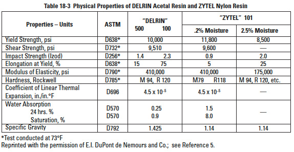
Table 18-3
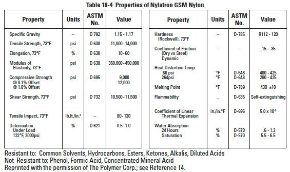
Table 18-4
Table 18-5
Table 18-6
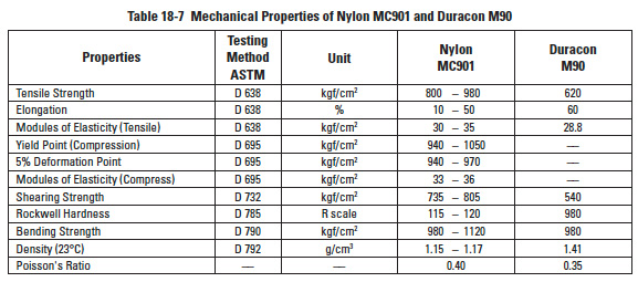
Table 18-7
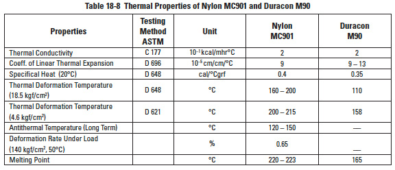
Table 18-8
Table 18-9
Table 18-10
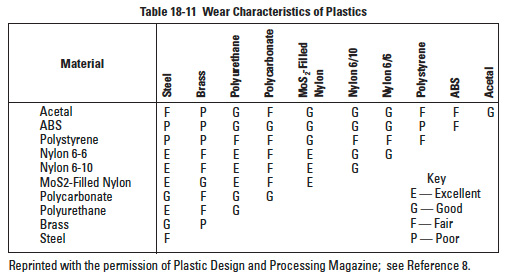
Table 18-11
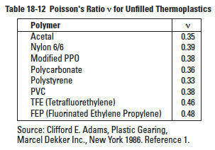
Table 18-12
Table 18-13
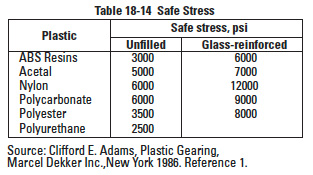
Table 18-14
Popular materials for plastic gears are acetal resins such as DELRIN*, Duracon M90; nylon resins such as ZYTEL*, NYLATRON**, MC901 and acetal copolymers such as CELCON***. The physical and mechanical properties of these materials vary with regard to strength, rigidity, dimensional stability, lubrication requirements, moisture absorption, etc. Standardized tabular data is available from various manufacturers' catalogs. Manufacturers in the U.S.A. provide this information in units customarily used in the U.S.A. In general, the data is less simplified and fixed than for the metals. This is because plastics are subject to wider formulation variations and are often regarded as proprietary compounds and mixtures. Tables 18-1, 18-2, 18-3, 18-4, 18-5, 18-6, 18-7, 18-8 and 18-9 are representative listings of physical and mechanical properties of gear plastics taken from a variety of sources. All reprinted tables are in their original units of measure.
It is common practice to use plastics in combination with different metals and materials other than plastics. Such is the case when gears have metal hubs, inserts, rims, spokes, etc. In these cases, one must be cognizant of the fact that plastics have an order of magnitude different coefficients of thermal expansion as well as density and modulus of elasticity. For this reason, Table 18-10 is presented.
Other properties and features that enter into consideration for gearing are given in Table 18-11 (Wear) and Table 18-12 (Poisson's Ratio).
Moisture has a significant impact on plastic properties as can be seen in Tables 18-1 thru 18-5. Ranking of plastics is given in Table 18-13. In this table, rate refers to expansion from dry to full moist condition. Thus, a 0.20% rating means a dimensional increase of 0.002 mm/mm. Note that this is only a rough guide, as exact values depend upon factors of composition and processing, both the raw material and gear molding. For example, it can be seen that the various types and grades of nylon can range from 0.07% to 2.0%. Table 18-14 lists safe stress values for a few basic plastics and the effect of glass fiber reinforcement.
It is important to stress the resistance to chemical corrosion of some plastic materials. These properties of some of materials used in the products presented in this catalog are further explored.
Nylon MC901
Nylon MC901 has almost the same level of antichemical corrosion property as Nylon resins. In general, it has a better antiorganic solvent property, but has a weaker antiacid property. The properties are as follows:
- For many nonorganic acids, even at low concentration at normal temperature, it should not be used without further tests.
- For nonorganic alkali at room temperature, it can be used to a certain level of concentration.
- For the solutions of nonorganic salts, we may apply them to a fairly high level of temperature and concentration.
- MC901 has better antiacid ability and stability in organic acids than in nonorganic acids, except for formic acid.
- MC901 is stable at room temperature in organic compounds of ester series and ketone series.
- It is also stable in mineral oil, vegetable oil and animal oil, at room temperature.
Duracon M90
This plastic has outstanding antiorganic properties. However, it has the disadvantage of having limited suitable adhesives. Its main properties are:
- Good resistance against nonorganic chemicals, but will be corroded by strong acids such as nitric, sulfuric and chloric acids.
- Household chemicals, such as synthetic detergents, have almost no effect on M90.
- M90 does not deteriorate even under long term operation in high temperature lubricating oil, except for some additives in high grade lubricants.
- With grease, M90 behaves the same as with oil lubricants.
Gear designers interested in using this material should be aware of properties regarding individual chemicals. Plastic manufacturers' technical information manuals should be consulted prior to making gear design decisions.
18.3 Choice Of Pressure Angles And ModulesEdit
Pressure angles of 14.5°, 20° and 25° are used in plastic gears. The 20° pressure angle is usually preferred due to its stronger tooth shape and reduced undercutting compared to the 14.5° pressure angle system. The 25° pressure angle has the highest load-carrying ability, but is more sensitive to center distance variation and hence runs less quietly. The choice is dependent on the application.
The determination of the appropriate module or diametral pitch is a compromise between a number of different design requirements. A larger module is associated with larger and stronger teeth. For a given pitch diameter, however, this also means a smaller number of teeth with a correspondingly greater likelihood of undercut at very low number of teeth. Larger teeth are generally associated with more sliding than smaller teeth.
On the other hand, smaller modules, which are associated with smaller teeth, tend to provide greater load sharing due to the compliance of plastic gears. However, a limiting condition would eventually be reached when mechanical interference occurs as a result of too much compliance. Smaller teeth are also more sensitive to tooth errors and may be more highly stressed.
A good procedure is probably to size the pinion first, since it is the more highly loaded member. It should be proportioned to support the required loads, but should not be over designed.
18.4 Strength Of Plastic Spur GearsEdit
In the following text, main consideration will be given to Nylon MC901 and Duracon M90. However, the basic equations used are applicable to all other plastic materials if the appropriate values for the factors are applied.
18.4.1 Bending Strength of Spur GearsEdit
Nylon MC901
The allowable tangential force F (kgf) at the pitch circle of a Nylon MC901 spur gear can be obtained from the Lewis formula.
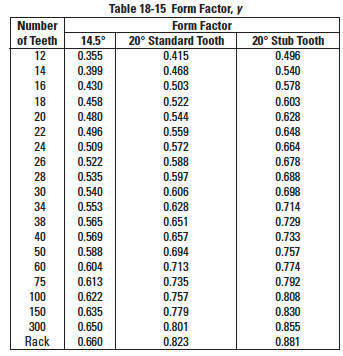
Table 18-15
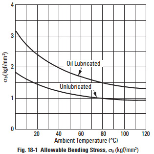
Figure 18-1
where:
m = Module (mm)
y = Form factor at pitch point (see Table 18-15)
b = Teeth width (mm)
σb = Allowable bending stress (kgf/mm²) (see Figure 18-1)
Duracon M90 The allowable tangential force F (kgf) at pitch circle of a Duracon M90 spur gear can also be obtained from the Lewis formula.
where:
m = Module (mm)
y = Form factor at pitch point (see Table 18-15)
b = Teeth width (mm)
σb = Allowable bending stress (kgf/mm²)
The allowable bending stress can be calculated by Equation (18-3):
Table 18-16
See also Table 18-16.
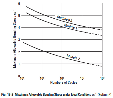
Figure 18-2
Figure 18-3
Figure 18-4
Table 18-17
Table 18-18
Table 18-19
where:
σb¹ = Maximum allowable bending stress under ideal condition (kgf/mm²) (see Figure 18-2)
CS = Working factor (see Table 18-17)
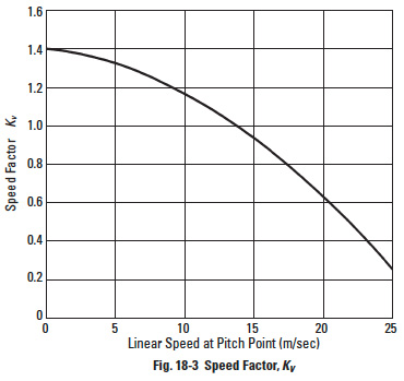
KV = Speed factor (see Figure 18-3)
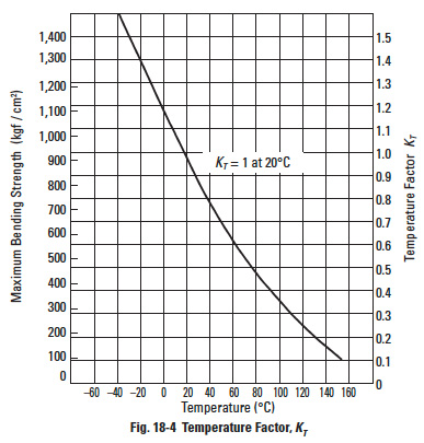
KT = Temperature factor (see Figure 18-4)
KL = Lubrication factor (see Table 18-18)
KM = Material factor (see Table 18-19)
Application Notes
In designing plastic gears, the effects of heat and moisture must be given careful consideration. The related problems are:
- Backlash
- Plastic gears have larger coefficients of thermal expansion. Also, they have an affinity to absorb moisture and swell. Good design requires allowance for a greater amount of backlash than for metal gears.
- Lubrication
- Most plastic gears do not require lubrication. However, temperature rise due to meshing may be controlled by the cooling effect of a lubricant as well as by reduction of friction. Often, in the case of high-speed rotational speeds, lubrication is critical.
- Plastic gear with metal mate
- If one of the gears of a mated pair is metal, there will be a heat sink that combats a high temperature rise. The effectiveness depends upon the particular metal, amount of metal mass, and rotational speed.
18.4.2 Surface Strength of Plastic Spur GearsEdit
Duracon M90
Duracon gears have less friction and wear when in an oil lubrication condition. However, the calculation of strength must take into consideration a no-lubrication condition. The surface strength using Hertz contact stress, Sc, is calculated by Equation (18-4).
Figure 18-5
Figure 18-6
where:
F = Tangential force on surface (kgf)
b = Tooth width (mm)
d = Pitch diameter of pinion (mm)
u = Gear ratio = z2 / z1
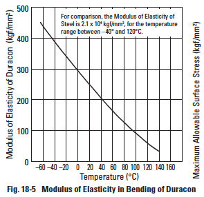
E = Modulus of elasticity of material (kgf/mm²) (see Figure 18-5)
α = Pressure angle
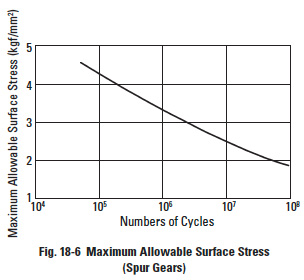
If the value of Hertz contact stress, Sc, is calculated by Equation (18-4) and the value falls below the curve of Figure 18-6, then it is directly applicable as a safe design. If the calculated value falls above the curve, the Duracon gear is unsafe.
Figure 18-6 is based upon data for a pair of Duracon gears: m = 2, v = 12 m/s, and operating at room temperature. For working conditions that are similar or better, the values in the figure can be used.
18.4.3 Bending Strength Of Plastic Bevel GearsEdit
Nylon MC901
The allowable tangential force at the pitch circle is calculated by Equation (18-5).
where:
m = module (mm)
Ra = Outer cone distance (mm)
b = Tooth width (mm)
y = Form factor at pitch point, which is obtained from Table 18-15 by computing the number of teeth of equivalent spur gear via Equation (18-6).
σb = Allowable bending stress
zV = Number of teeth of equivalent spur gear
δ = Pitch cone angle (degree)
Other variables may be calculated the same way as for spur gears.
Duracon M90
The allowable tangential force F (kgf) on pitch circle of Duracon M90 bevel gears can be obtained from Equation (18-7).
and y = Form factor at pitch point, which is obtained from Table 18-15 by first computing the number of teeth of equivalent spur gear using Equation (18-6).
Other variables may be calculated the same way as for spur gears.
18.4.4 Bending Strength Of Plastic Worm GearsEdit
Nylon MC901
Generally, the worm is much stronger than the worm gear. Therefore, it is necessary to calculate the strength of only the worm gear.
The allowable tangential force F (kgf) at the pitch circle of the worm gear is obtained from Equation (18-8).
Table 18-20
where: mn = Normal module (mm)
y = Form factor at pitch point, which is obtained from Table 18-15 by first computing the number of teeth of equivalent spur gear using Equation (18-9).
zV = Number of teeth of equivalent spur gear
γ = Lead angle
Worm meshes have relatively high sliding velocities, which induces a high temperature rise. This causes a sharp decrease in strength and abnormal friction wear. This is particularly true of an all plastic mesh. Therefore, sliding speeds must be contained within recommendations of Table 18-20.
Lubrication of plastic worms is vital, particularly under high load and continuous operation.
18.4.5 Strength Of Plastic KeywayEdit
Fastening of a plastic gear to the shaft is often done by means of a key and keyway. Then, the critical thing is the stress level imposed upon the keyway sides. This is calculated by Equation (18-10).
where:
σ = Pressure on the keyway sides (kgf/cm²)
T = Transmitted torque (kgf • m)
d = Diameter of shaft (cm)
l = Effective length of keyway (cm)
h = Depth of keyway (cm)
The maximum allowable surface pressure for MC901 is 200 kgf/cm², and this must not be exceeded. Also, the keyway's corner must have a suitable radius to avoid stress concentration. The distance from the root of the gear to the bottom of the keyway should be at least twice the tooth whole depth, h.
Keyways are not to be used when the following conditions exist:
- Excessive keyway stress
- High ambient temperature
- High impact
- Large outside diameter gears
When above conditions prevail, it is expedient to use a metallic hub in the gear. Then, a keyway may be cut in the metal hub.
A metallic hub can be fixed in the plastic gear by several methods:
- Press the metallic hub into the plastic gear, ensuring fastening with a knurl or screw.
- Screw fasten metal discs on each side of the plastic gear.
- Thermofuse the metal hub to the gear.
18.5 Effect Of Part Shrinkage On Plastic Gear DesignEdit
The nature of the part and the molding operation have a significant effect on the molded gear. From the design point of view, the most important effect is the shrinkage of the gear relative to the size of the mold cavity.
Gear shrinkage depends upon mold proportions, gear geometry, material, ambient temperature and time. Shrinkage is usually expressed in millimeters per millimeter. For example, if a plastic gear with a shrinkage rate of 0.022 mm/mm has a pitch diameter of 50 mm while in the mold, the pitch diameter after molding will be reduced by (50)(0.022) or 1.1 mm, and becomes 48.9 mm after it leaves the mold.
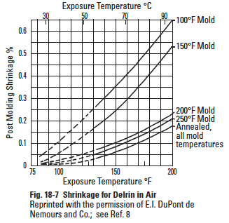
Figure 18-7
Depending upon the material and the molding process, shrinkage rates ranging from about 0.001 mm/mm to 0.030 mm/mm occur in plastic gears (see Table 18-1 and Figure 18-7). Sometimes shrinkage rates are expressed as a percentage. For example, a shrinkage rate of 0.0025 mm/mm can be stated as a 0.25% shrinkage rate.
The effect of shrinkage must be anticipated in the design of the mold and requires expert knowledge. Accurate and specific treatment of this phenomenon is a result of years of experience in building molds for gears; hence, details go beyond the scope of this presentation.
In general, the final size of a molded gear is a result of the following factors:
- Plastic material being molded.
- Injection pressure.
- Injection temperature.
- Injection hold time.
- Mold cure time and mold temperature.
- Configuration of part (presence of web, insert, spokes, ribs, etc.).
- Location, number and size of gates.
- Treatment of part after molding.
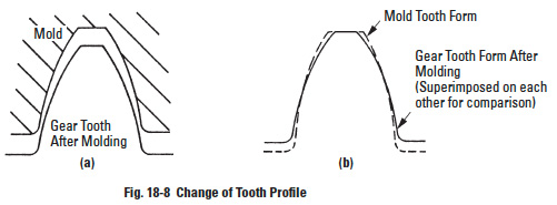
Figure 18-8
From the above, it becomes obvious that with the same mold – by changing molding parameters – parts of different sizes can be produced.
The form of the gear tooth itself changes as a result of shrinkage, irrespective of it shrinking away from the mold, as shown in Figure 18-8. The resulting gear will be too thin at the top and too thick at the base. The pressure angle will have increased, resulting in the possibility of binding, as well as greater wear.
In order to obtain an idea of the effect of part shrinkage subsequent to molding, the following equations are presented where the primes refer to quantities after the shrinkage occurred:
where:
s * = shrinkage rate (mm/mm)
m = module
α = pressure angle
d = pitch diameter (mm)
p' = circular pitch (mm)
z = number of teeth
It follows that a hob generating the electrode for a cavity which will produce a post shrinkage standard gear would need to be of a nonstandard configuration.
Let us assume that an electrode is cut for a 20° pressure angle, module 1, 64 tooth gear which will be made of acetal (s * = 0.022) and will have 64 mm pitch diameter after molding.
cos α = cos α (1 + s *) = 0.93969262 (1 + 0.022) = 0.96036
therefore, α = 16°11' pressure angle
The pitch diameter of the electrode, therefore, will be:
d = zm = 64 x 1.0225 = 65.44 mm
For the sake of simplicity, we are ignoring the correction which has to be made to compensate for the electrode gap which results in the cavity being larger than the electrode.
The shrinking process can give rise to residual stresses within the gear, especially if it has sections of different thicknesses. For this reason, a hubless gear is less likely to be warped than a gear with a hub.
If necessary, a gear can be annealed after molding in order to relieve residual stresses. However, since this adds another operation in the manufacturing of the gear, annealing should be considered only under the following circumstances:
If maximum dimensional stability is essential.
- If the stresses in the gear would otherwise exceed the design limit.
- If close tolerances and high-temperature operation makes annealing necessary.
Annealing adds a small amount of lubricant within the gear surface region. If the prior gear lubrication is marginal, this can be helpful.
18.6 Proper Use Of Plastic GearsEdit
18.6.1 BacklashEdit
Due to the thermal expansion of plastic gears, which is significantly greater than that of metal gears, and the effects of tolerances, one should make sure that meshing gears do not bind in the course of service. Several means are available for introducing backlash into the system. Perhaps the simplest is to enlarge center distance. Care must be taken, however, to ensure that the contact ratio remains adequate.
It is possible also to thin out the tooth profile during manufacturing, but this adds to the manufacturing cost and requires careful consideration of the tooth geometry.
To some extent, the flexibility of the bearings and clearances can compensate for thermal expansion. If a small change in center distance is necessary and feasible, it probably represents the best and least expensive compromise.
18.6.2 Environment and TolerancesEdit
In any discussion of tolerances for plastic gears, it is necessary to distinguish between manufacturing tolerances and dimensional changes due to environmental conditions.
As far as manufacturing is concerned, plastic gears can be made to high accuracy, if desired. For injection molded gears, Total Composite Error can readily be held within a range of roughly 0.075 – 0.125 mm, with a corresponding Tooth-to-Tooth Composite Error of about 0.025 – 0.050 mm. Higher accuracies can be obtained if the more expensive filled materials, mold design, tooling and quality control are used.
In addition to thermal expansion changes, there are permanent dimensional changes as the result of moisture absorption. Also, there are dimensional changes due to compliance under load. The coefficient of thermal expansion of plastics is on the order of four to ten times those of metals (see Tables 18-3 and 18-10). In addition, most plastics are hygroscopic (i.e., absorb moisture) and dimensional changes on the order of 0.1% or more can develop in the course of time, if the humidity is sufficient. As a result, one should attempt to make sure that a tolerance which is specified is not smaller than the inevitable dimensional changes which arise as a result of environmental conditions. At the same time, the greater compliance of plastic gears, as compared to metal gears, suggests that the necessity for close tolerances need not always be as high as those required for metal gears.
18.6.3 Avoiding Stress ConcentrationEdit
In order to minimize stress concentration and maximize the life of a plastic gear, the root fillet radius should be as large as possible, consistent with conjugate gear action. Sudden changes in cross section and sharp corners should be avoided, especially in view of the possibility of additional residual stresses which may have occurred in the course of the molding operation.
18.6.4 Metal InsertsEdit
Injection molded metal inserts are used in plastic gears for a variety of reasons:
- To avoid an extra finishing operation.
- To achieve greater dimensional stability, because the metal will shrink less and is not sensitive to moisture; it is, also, a better heat sink.
- To provide greater load-carrying capacity.
- To provide increased rigidity.
- To permit repeated assembly and disassembly.
- To provide a more precise bore to shaft fit.
Inserts can be molded into the part or subsequently assembled. In the case of subsequent insertion of inserts, stress concentrations may be present which may lead to cracking of the parts. The interference limits for press fits must be obeyed depending on the material used; also, proper minimum wall thicknesses around the inserts must be left. The insertion of inserts may be accomplished by ultrasonically driving in the insert. In this case, the material actually melts into the knurling at the insert periphery.
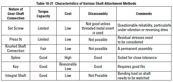
Table 18-21
Inserts are usually produced by screw machines and made of aluminum or brass. It is advantageous to attempt to match the coefficient of thermal expansion of the plastic to the materials used for inserts. This will reduce the residual stresses in the plastic part of the gear during contraction while cooling after molding.
When metal inserts are used, generous radii and fillets in the plastic gear are recommended to avoid stress concentration. It is also possible to use other types of metal inserts, such as self-threading, self-tapping screws, press fits and knurled inserts. One advantage of the first two of these is that they permit repeated assembly and disassembly without part failure or fatigue.
18.6.5 Attachment Of Plastic Gears to ShaftsEdit
Several methods of attaching gears to shafts are in common use. These include splines, keys, integral shafts, set screws, and plain and knurled press fits. Table 18-21 lists some of the basic characteristics of each of these fastening methods.
18.6.6 LubricationEdit
Depending on the application, plastic gears can operate with continuous lubrication, initial lubrication, or no lubrication. According to L.D. Martin ("Injection Molded Plastic Gears", Plastic Design and Processing, 1968; Part 1, August, pp 38-45; Part 2, September, pp. 33-35):
- All gears function more effectively with lubrication and will have a longer service life.
- A light spindle oil (SAE 10) is generally recommended as are the usual lubricants; these include silicone and hydrocarbon oils, and in some cases cold water is acceptable as well.
- Under certain conditions, dry lubricants such as molybdenum disulfide, can be used to reduce tooth friction.
Ample experience and evidence exist substantiating that plastic gears can operate with a metal mate without the need of a lubricant, as long as the stress levels are not exceeded. It is also true that in the case of a moderate stress level, relative to the materials rating, plastic gears can be meshed together without a lubricant. However, as the stress level is increased, there is a tendency for a localized plastic-to-plastic welding to occur, which increases friction and wear. The level of this problem varies with the particular type of plastic.
A key advantage of plastic gearing is that, for many applications, running dry is adequate. When a situation of stress and shock level is uncertain, using the proper lubricant will provide a safety margin and certainly will cause no harm. The chief consideration should be in choosing a lubricant's chemical compatibility with the particular plastic. Least likely to encounter problems with typical gear oils and greases are: nylons, Delrins (acetals), phenolics, polyethylene and polypropylene. Materials requiring caution are: polystyrene, polycarbonates, polyvinyl chloride and ABS resins. An alternate to external lubrication is to use plastics fortified with a solid state lubricant. Molybdenum disulfide in nylon and acetal are commonly used. Also, graphite, colloidal carbon and silicone are used as fillers.
In no event should there be need of an elaborate sophisticated lubrication system such as for metal gearing. If such a system is contemplated, then the choice of plastic gearing is in question. Simplicity is the plastic gear's inherent feature.
18.6.7 Molded vs. Cut Plastic GearsEdit
Although not nearly as common as the injection molding process, both thermosetting and thermoplastic plastic gears can be readily machined. The machining of plastic gears can be considered for high precision parts with close tolerances and for the development of prototypes for which the investment in a mold may not be justified. Standard stock gears of reasonable precision are produced by using blanks molded with brass inserts, which are subsequently hobbed to close tolerances.
When to use molded gears vs. cut plastic gears is usually determined on the basis of production quantity, body features that may favor molding, quality level and unit cost. Often, the initial prototype quantity will be machine cut, and investment in molding tools is deferred until the product and market is assured. However, with some plastics this approach can encounter problems.
The performance of molded vs. cut plastic gears is not always identical. Differences occur due to subtle causes. Bar stock and molding stock may not be precisely the same. Molding temperature can have an effect. Also, surface finishes will be different for cut vs. molded gears. And finally, there is the impact of shrinkage with molding which may not have been adequately compensated.
18.6.8 Elimination of Gear NoiseEdit
Incomplete conjugate action and/or excessive backlash are usually the source of noise. Plastic molded gears are generally less accurate than their metal counterparts. Furthermore, due to the presence of a larger Total Composite Error, there is more backlash built into the gear train.
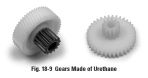
To avoid noise, more resilient material, such as urethane, can be used. Figure 18-9 shows several gears made of urethane which, in mesh with Delrin gears, produce a practically noiseless gear train. The face width of the urethane gears must be increased correspondingly to compensate for lower load carrying ability of this material.
18.7 Mold ConstructionEdit
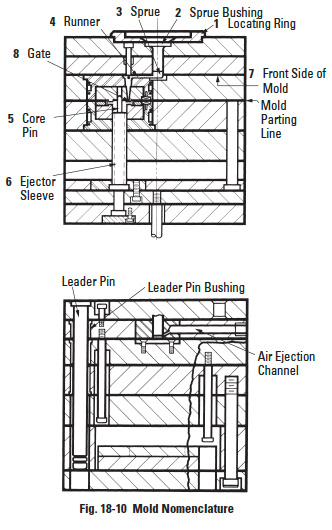
Depending on the quantity of gears to be produced, a decision has to be made to make one single cavity or a multiplicity of identical cavities. If more than one cavity is involved, these are used as "family molds" inserted in mold bases which can accommodate a number of cavities for identical or different parts. Since special terminology will be used, we shall first describe the elements shown in Figure 18-10.
Locating Ring is the element which assures the proper location of the mold on the platen with respect to the nozzle which injects the molten plastic.
- Sprue Bushing is the element which mates with the nozzle. It has a spherical or flat receptacle which accurately mates with the surface of the nozzle.
- Sprue is the channel in the sprue bushing through which the molten plastic is injected.
- Runner is the channel which distributes material to different cavities within the same mold base.
- Core Pin is the element which, by its presence, restricts the flow of plastic; hence, a hole or void will be created in the molded part.
- Ejector Sleeves are operated by the molding machine. These have a relative motion with respect to the cavity in the direction which will cause ejection of the part from the mold.
- Front Side is considered the side on which the sprue bushing and the nozzle are located.
- Gate is the orifice through which the molten plastic enters the cavity.
- Vent (not visible due to its small size) is a minuscule opening through which the air can be evacuated from the cavity as the molten plastic fills it. The vent is configured to let air escape, but does not fill up with plastic.
The location of the gate on the gear is extremely important. If a side gate is used, as shown in Figure 18-11, the material is injected in one spot and from there it flows to fill out the cavity. This creates a weld line opposite to the gate. Since the plastic material is less fluid at that point in time, it will be of limited strength where the weld is located. Furthermore, the shrinkage of the material in the direction of the flow will be different from that perpendicular to the flow. As a result, a side-gated gear or rotating part will be somewhat elliptical rather than round.
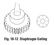
In order to eliminate this problem, "diaphragm gating" can be used, which will cause the injection of material in all directions at the same time (Figure 18-12). The disadvantage of this method is the presence of a burr at the hub and no means of support of the core pin because of the presence of the sprue.
Figure 18-14
Figure 18-14 cont.
Figure 18-14 cont.
Figure 18-15
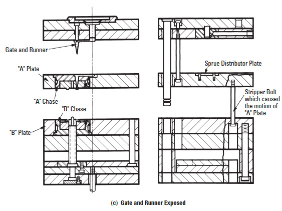
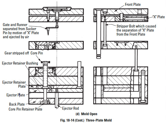
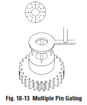
The best, but most elaborate, way is "multiple pin gating" (Figure 18-13). In this case, the plastic is injected at several places symmetrically located. This will assure reasonable viscosity of plastic when the material welds, as well as create uniform shrinkage in all directions. The problem is the elaborate nature of the mold arrangement – so called 3-plate molds, in Figure 18-14, 18-14 part 2, and 18-14 part 3 – accompanied by high costs. If precision is a requirement, this way of molding is a must, particularly if the gears are of a larger diameter. To compare the complexity of a 3-plate mold with a 2-plate mold, which is used for edge gating, Figure 18-15 can serve as an illustration.
Section 19: Features of tooth surface contactEdit
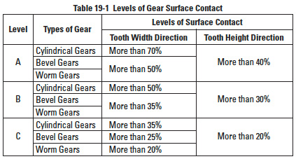
Table 19-1
Tooth surface contact is critical to noise, vibration, efficiency, strength, wear and life. To obtain good contact, the designer must give proper consideration to the following features:
- Modifying the Tooth Shape
Improve tooth contact by crowning or relieving.
- Using Higher Precision Gear
Specify higher accuracy by design. Also, specify that the manufacturing process is to include grinding or lapping.
- Controlling the Accuracy of the Gear Assembly
Specify adequate shaft parallelism and perpendicularity of the gear housing (box or structure).
Surface contact quality of spur and helical gears can be reasonably controlled and verified through piece part inspection. However, for the most part, bevel and worm gears cannot be equally well inspected. Consequently, final inspection of bevel and worm mesh tooth contact in assembly provides a quality criterion for control. Then, as required, gears can be axially adjusted to achieve desired contact.
JIS B 1741 classifies surface contact into three levels, as presented in Table 19-1. The percentage in Table 19-1 considers only the effective width and height of teeth.
19.1 Surface Contact Of Spur And Helical MeshesEdit
A check of contact is, typically, only done to verify the accuracy of the installation, rather than the individual gears. The usual method is to blue dye the gear teeth and operate for a short time. This reveals the contact area for inspection and evaluation.
19.2 Surface Contact Of A Bevel GearEdit
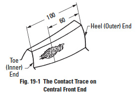
It is important to check the surface contact of a bevel gear both during manufacturing and again in final assembly. The method is to apply a colored dye and observe the contact area after running. Usually some load is applied, either the actual or applied braking, to realize a realistic contact condition. Ideal contact favors the toe end under no or light load, as shown in Figure 19-1; and, as load is increased to full load, contact shifts to the central part of the tooth width.
Even when a gear is ideally manufactured, it may reveal poor surface contact due to lack of precision in housing or improper mounting position, or both. Usual major faults are:
- Shafts are not intersecting, but are skew (offset error).
- Shaft angle error of gear box.
- Mounting distance error.
Errors 1 and 2 can be corrected only by reprocessing the housing/mounting. Error 3 can be corrected by adjusting the gears in an axial direction. All three errors may be the cause of improper backlash.
19.2.1 The Offset Error of Shaft AlignmentEdit
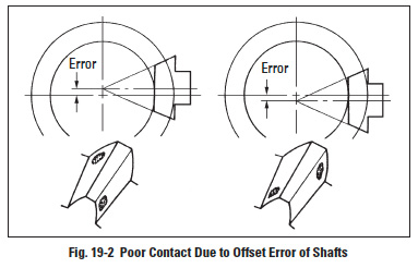
If a gear box has an offset error, then it will produce crossed end contact, as shown in Figure 19-2. This error often appears asif error is in the gear tooth orientation.
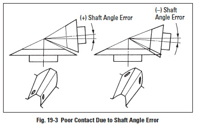
19.2.2 The Shaft Angle Error of Gear BoxEdit
As Figure 19-3 shows, the contact trace will move toward the toe end if the shaft angle error is positive; the contact trace will move toward the heel end if the shaft angle error is negative.
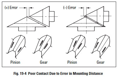
19.2.3 Mounting Distance ErrorEdit
When the mounting distance of the pinion is a positive error, the contact of the pinion will move towards the tooth root, while the contact of the mating gear will move toward the top of the tooth. This is the same situation as if the pressure angle of the pinion is smaller than that of the gear. On the other hand, if the mounting distance of the pinion has a negative error, the contact of the pinion will move toward the top and that of the gear will move toward the root. This is similar to the pressure angle of the pinion being larger than that of the gear. These errors may be diminished by axial adjustment with a backing shim. The various contact patterns due to mounting distance errors are shown in Figure 19-4.
Mounting distance error will cause a change of backlash; positive error will increase backlash; and negative, decrease. Since the mounting distance error of the pinion affects the surface contact greatly, it is customary to adjust the gear rather than the pinion in its axial direction.
19.3 Surface Contact Of Worm And Worm GearEdit
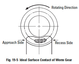
There is no specific Japanese standard concerning worm gearing, except for some specifications regarding surface contact in JIS B 1741. Therefore, it is the general practice to test the tooth contact and backlash with a tester. Figure 19-5 shows the ideal contact for a worm gear mesh.
From Figure 19-5, we realize that the ideal portion of contact inclines to the receding side. The approaching side has a smaller contact trace than the receding side. Because the clearance in the approaching side is larger than in the receding side, the oil film is established much easier in the approaching side. However, an excellent worm gear in conjunction with a defective gear box will decrease the level of tooth contact and the performance.
There are three major factors, besides the gear itself, which may influence the surface contact:
- Shaft Angle Error.
- Center Distance Error.
- Mounting Distance Error of Worm Gear.
Errors number 1 and number 2 can only be corrected by remaking the housing. Error number 3 may be decreased by adjusting the worm gear along the axial direction. These three errors introduce varying degrees of backlash.
19.3.1. Shaft Angle ErrorEdit
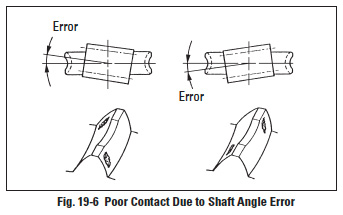
If the gear box has a shaft angle error, then it will produce crossed contact as shown in Figure 19-6. A helix angle error will also produce a similar crossed contact.
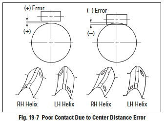
19.3.2 Center Distance ErrorEdit
Even when exaggerated center distance errors exist, as shown in Figure 19-7, the results are crossed end contacts. Such errors not only cause bad contact but also greatly influence backlash. A positive center distance error causes increased backlash. A negative error will decrease backlash and may result in a tight mesh, or even make it impossible to assemble.
19.3.3 Mounting Distance ErrorEdit
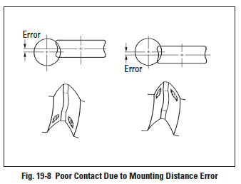
Figure 19-8 shows the resulting poor contact from mounting distance error of the worm gear. From the figure, we can see the contact shifts toward the worm gear tooth's edge. The direction of shift in the contact area matches the direction of worm gear mounting error. This error affects backlash, which tends to decrease as the error increases. The error can be diminished by microadjustment of the worm gear in the axial direction.
Section 20: Lubrication of gearsEdit
The purpose of lubricating gears is as follows:
- Promote sliding between teeth to reduce the coefficient of friction (µ).
- Limit the temperature rise caused by rolling and sliding friction.
To avoid difficulties such as tooth wear and premature failure, the correct lubricant must be chosen.
20.1 Methods Of LubricationEdit
There are three gear lubrication methods in general use:
- Grease lubrication.
- Splash lubrication (oil bath method).
- Forced oil circulation lubrication.
Table 20-1A
Table 20-1B
There is no single best lubricant and method. Choice depends upon tangential speed (m/s) and rotating speed (rpm). At low speed, grease lubrication is a good choice. For medium and high speeds, splash lubrication and forced circulation lubrication are more appropriate, but there are exceptions. Sometimes, for maintenance reasons, a grease lubricant is used even with high speed. Tables 20-1A and 20-1B presents lubricants, methods and their applicable ranges of speed.
The following is a brief discussion of the three lubrication methods.
20.1.1 Grease LubricationEdit
Grease lubrication is suitable for any gear system that is open or enclosed, so long as it runs at low speed. There are three major points regarding grease:
- Choosing a lubricant with suitable viscosity. A lubricant with good fluidity is especially effective in an enclosed system.
- Not suitable for use under high load and continuous operation. The cooling effect of grease is not as good as lubricating oil. So it may become a problem with temperature rise under high load and continuous operating conditions.
- Proper quantity of grease. There must be sufficient grease to do the job. However, too much grease can be harmful, particularly in an enclosed system. Excess grease will cause agitation, viscous drag and result in power loss.
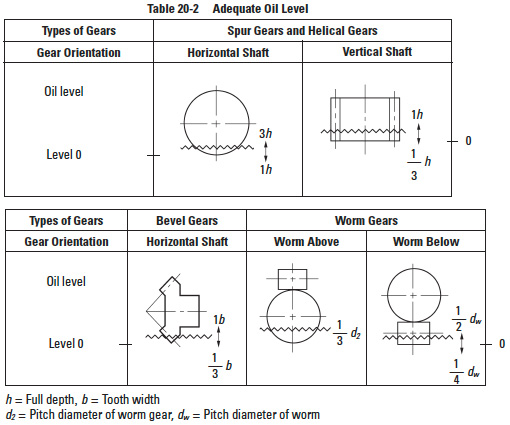
Table 20-2
20.1.2 Splash LubricationEdit
Splash lubrication is used with an enclosed system. The rotating gears splash lubricant onto the gear system and bearings. It needs at least 3 m/s tangential speed to be effective. However, splash lubrication has several problems, two of them being oil level and temperature limitation.
- Oil level:
- There will be excessive agitation loss if the oil level is too high. On the other hand, there will not be effective lubrication or ability to cool the gears if the level is too low. Table 20-2 shows guide lines for proper oil level. Also, the oil level during operation must be monitored, as contrasted with the static level, in that the oil level will drop when the gears are in motion. This problem may be countered by raising the static level of lubricant or installing an oil pan.
- Temperature limitation:
- The temperature of a gear system may rise because of friction loss due to gears, bearings and lubricant agitation. Rising temperature may cause one or more of the following problems:
- Lower viscosity of lubricant.
- Accelerated degradation of lubricant.
- Deformation of housing, gears and shafts.
- Decreased backlash.
- New high-performance lubricants can withstand up to 80 to 90°C. This temperature can be regarded as the limit. If the lubricant's temperature is expected to exceed this limit, cooling fins should be added to the gear box, or a cooling fan incorporated into the system.
20.1.3 Forced-Circulation LubricationEdit
Forced-circulation lubrication applies lubricant to the contact portion of the teeth by means of an oil pump. There are drop, spray and oil mist methods of application.
- Drop method:
- An oil pump is used to suck-up the lubricant and then directly drop it on the contact portion of the gears via a delivery pipe.
- Spray method:
- An oil pump is used to spray the lubricant directly on the contact area of the gears.
- Oil mist method:
- Lubricant is mixed with compressed air to form an oil mist that is sprayed against the contact region of the gears. It is especially suitable for highspeed gearing.
Oil tank, pump, filter, piping and other devices are needed in the forcedlubrication system. Therefore, it is used only for special high-speed or large gear box applications. By filtering and cooling the circulating lubricant, the right viscosity and cleanliness can be maintained. This is considered to be the best way to lubricate gears.
Table 20-3
Table 20-4
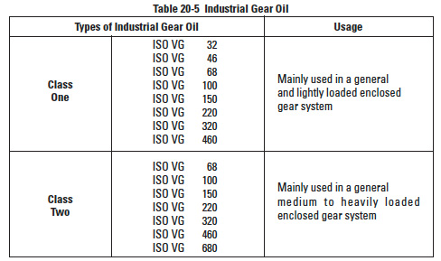
Table 20-5
Table 20-6
Table 20-7
Table 20-8
Table 20-9
Table 20-10
20.2 Gear LubricantsEdit
An oil film must be formed at the contact surface of the teeth to minimize friction and to prevent dry metal-to-metal contact. The lubricant should have the properties listed in Table 20-3.
20.2.1 Viscosity of LubricantEdit
The correct viscosity is the most important consideration in choosing a proper lubricant. The viscosity grade of industrial lubricant is regulated in JIS K 2001. Table 20-4 expresses ISO viscosity grade of industrial lubricants.
JIS K 2219 regulates the gear oil for industrial and automobile use. Table 20-5 shows the classes and viscosities for industrial gear oils.
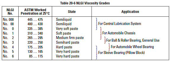
JIS K 2220 regulates the specification of grease which is based on NLGI viscosity ranges. These are shown in Table 20-6.
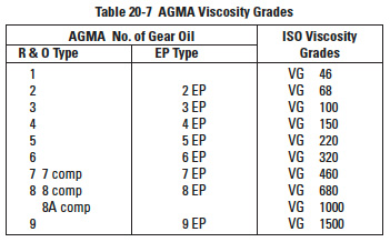
Besides JIS viscosity classifications, Table 20-7 contains AGMA viscosity grades and their equivalent ISO viscosity grades.
20.2.2 Selection Of LubricantEdit
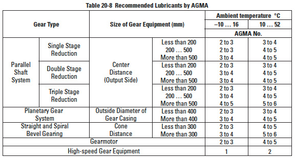
It is practical to select a lubricant by following the catalog or technical manual of the manufacturer. Table 20-8 is the application guide from AGMA 250.03 "Lubrication of Industrial Enclosed Gear Drives".
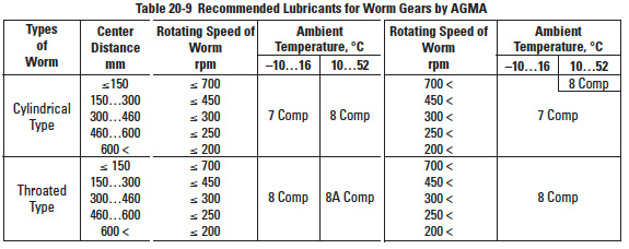
Table 20-9 is the application guide chart for worm gears from AGMA 250.03.
Table 20-10 expresses the reference value of viscosity of lubricant used in the equations for the strength of worm gears in JGMA 405-01.
Section 21: Gear noiseEdit
There are several causes of noise. The noise and vibration in rotating gears, especially at high loads and high speeds, need to be addressed. Following are ways to reduce the noise. These points should be considered in the design stage of gear systems.
- Use High-Precision Gears
- Reduce the pitch error, tooth profile error, runout error and lead error.
- Grind teeth to improve the accuracy as well as the surface finish.
- Use Better Surface Finish on Gears
- Grinding, lapping and honing the tooth surface, or running in gears in oil for a period of time can also improve the smoothness of tooth surface and reduce the noise.
- Ensure a Correct Tooth Contact
- Crowning and relieving can prevent end contact.
- Proper tooth profile modification is also effective.
- Eliminate impact on tooth surface.
- Have A Proper Amount of Backlash
- A smaller backlash will help reduce pulsating transmission.
- A bigger backlash, in general, causes less problems.
- Increase the Contact Ratio
- Bigger contact ratio lowers the noise. Decreasing pressure angle and/or increasing tooth depth can produce a larger contact ratio.
- Enlarging overlap ratio will reduce the noise. Because of this relationship, a helical gear is quieter than the spur gear and a spiral bevel gear is quieter than the straight bevel gear.
- Use Small Gears
- Adopt smaller module gears and smaller outside diameter gears.
- Use High-Rigidity Gears
- Increasing face width can give a higher rigidity that will help in reducing noise.
- Reinforce housing and shafts to increase rigidity.
- Use High-Vibration-Damping Material
- Plastic gears will be quiet in light load, low speed operation.
- Cast iron gears have lower noise than steel gears.
- Apply Suitable Lubrication
- Lubricate gears sufficiently.
- High-viscosity lubricant will have the tendency to reduce the noise.
- Lower Load and Speed
- Lowering rpm and load as far as possible will reduce gear noise.


